SR950 V3 increases memory
Confirm the device
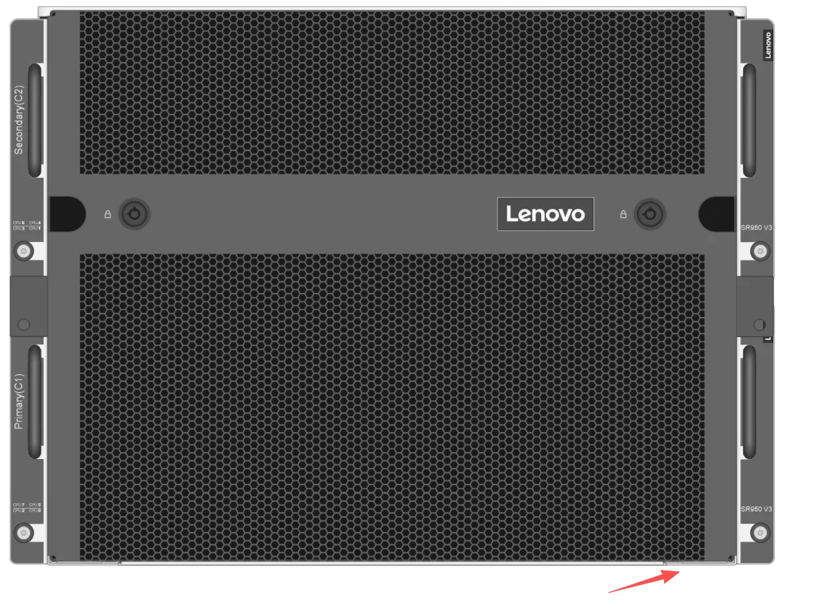
There is a removable information card at the bottom of the device to check whether the device serial number is correct
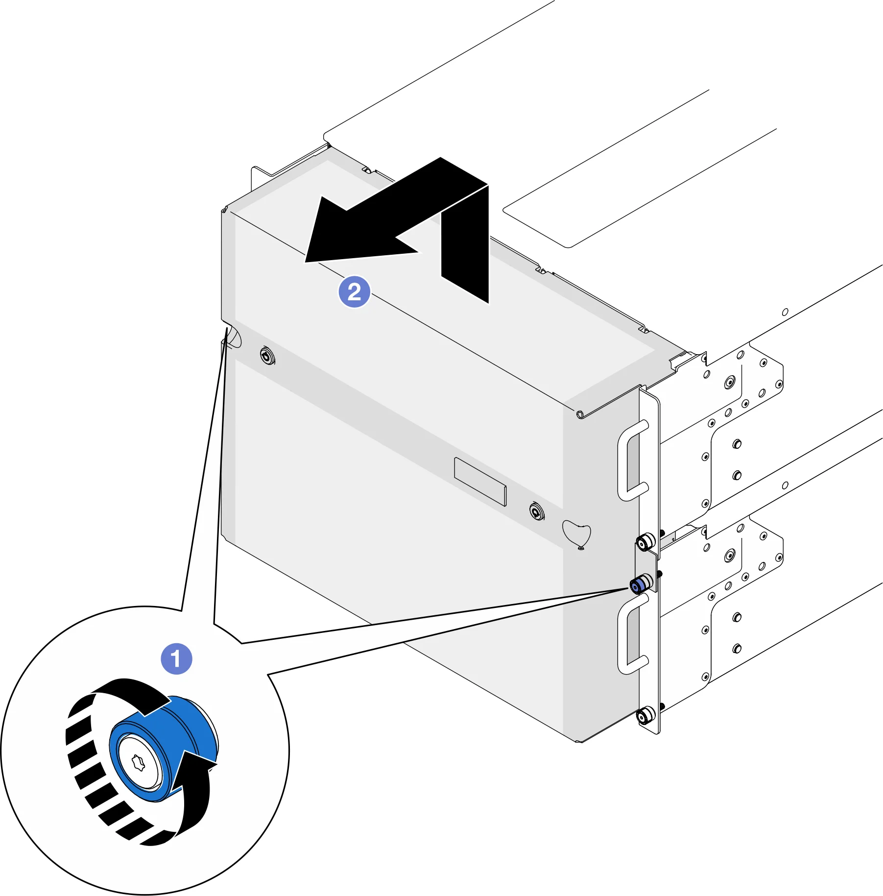
Remove the safety baffle
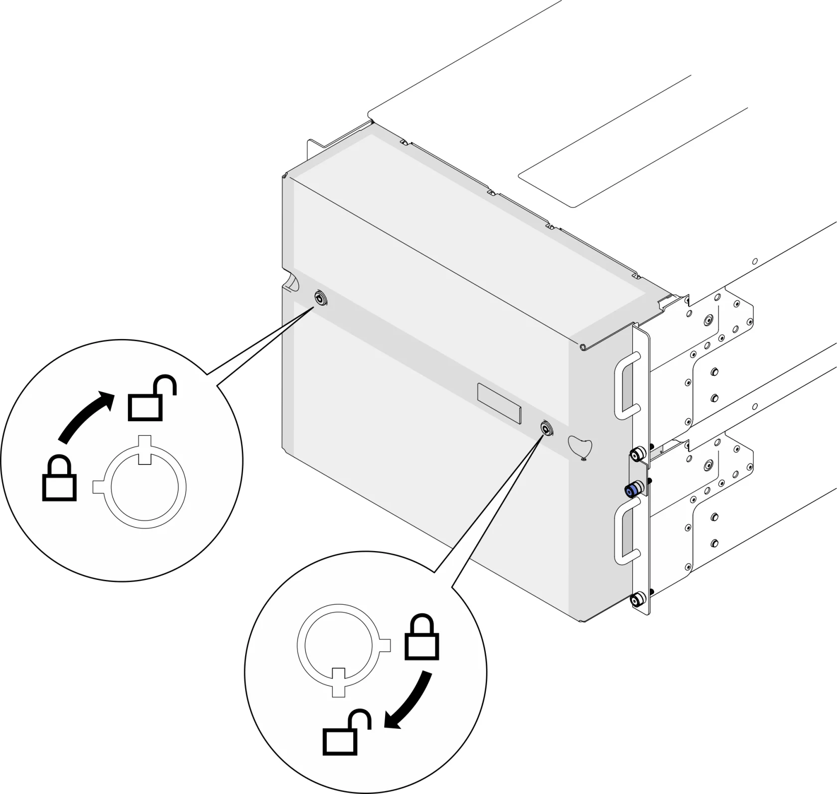
Unlock the safety baffle
Check whether the device is powered off (the on/off light flashes slowly (about once per second)) and press the ID light button to light up the device ID light
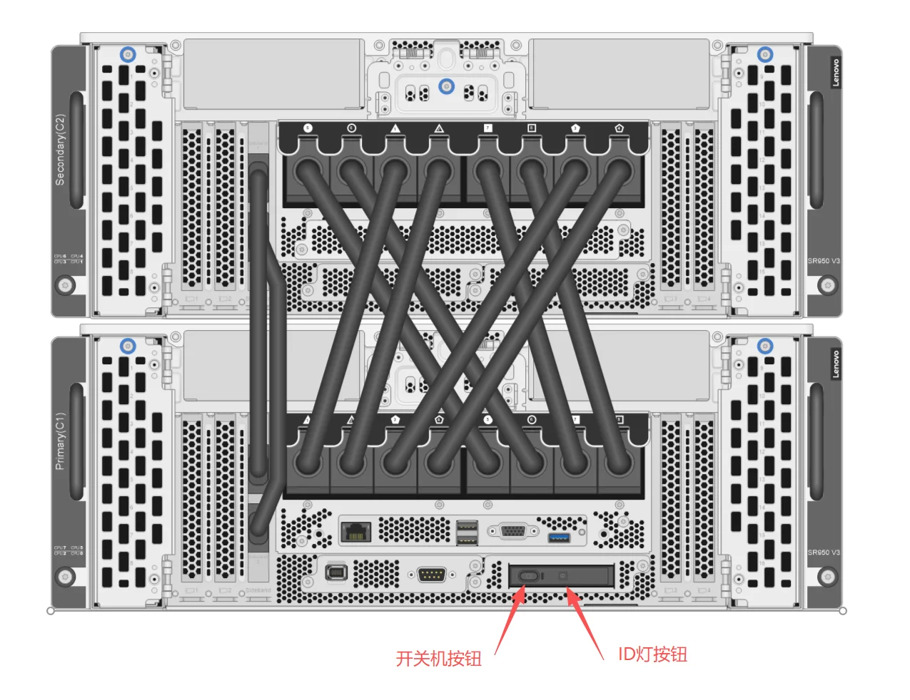
- Left indication: Power on button
- Right indication: ID light button
Remove the rear cable
Remove all data cables behind the device after marking them
Power cable: Make sure the power indicator is only IN, remove the power cable from the lower chassis first, and then remove the power cable from the upper chassis
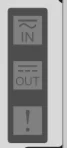
电源指示灯示意图
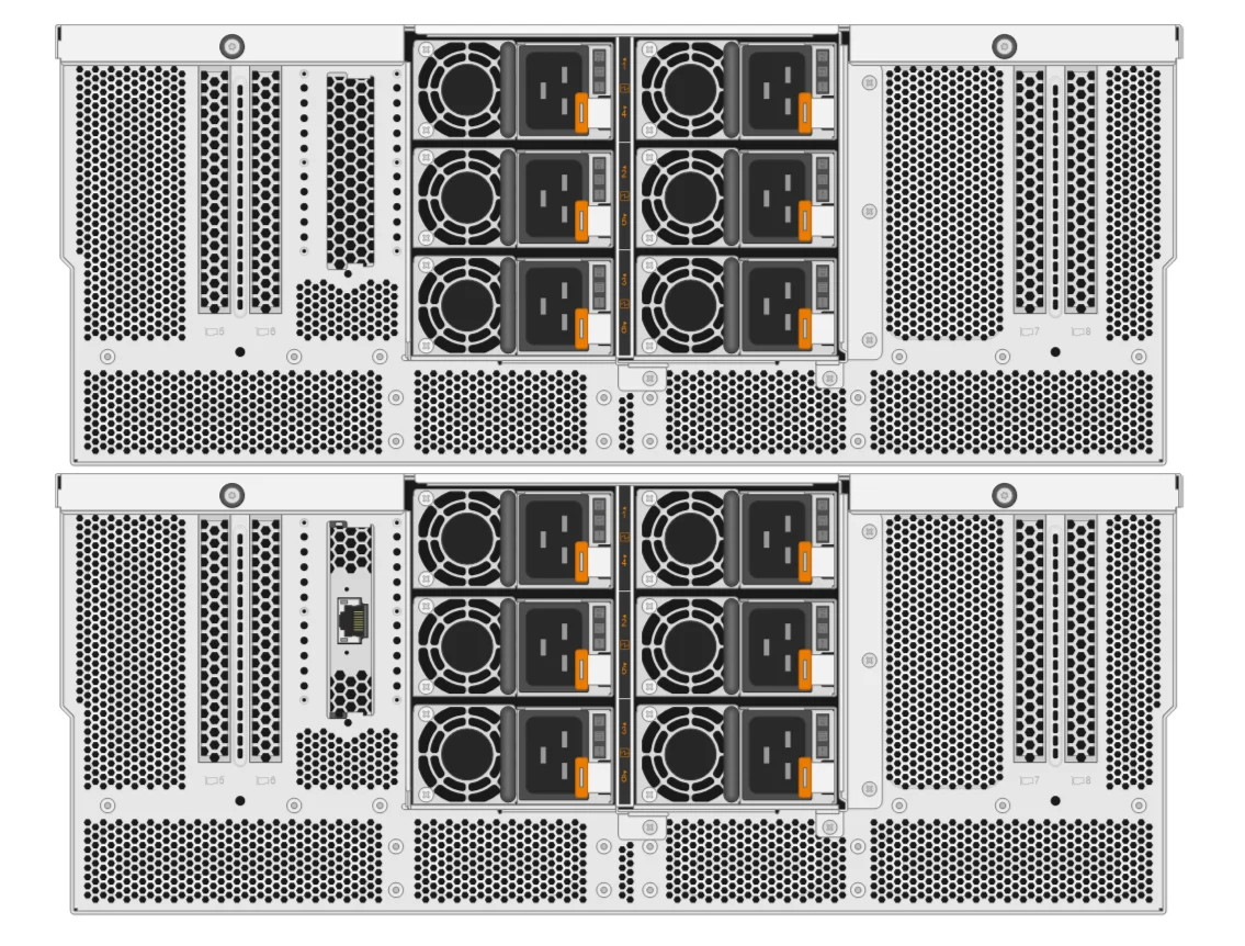
Remove the front cable
Removing the Front Connect Cables (2 Pieces)
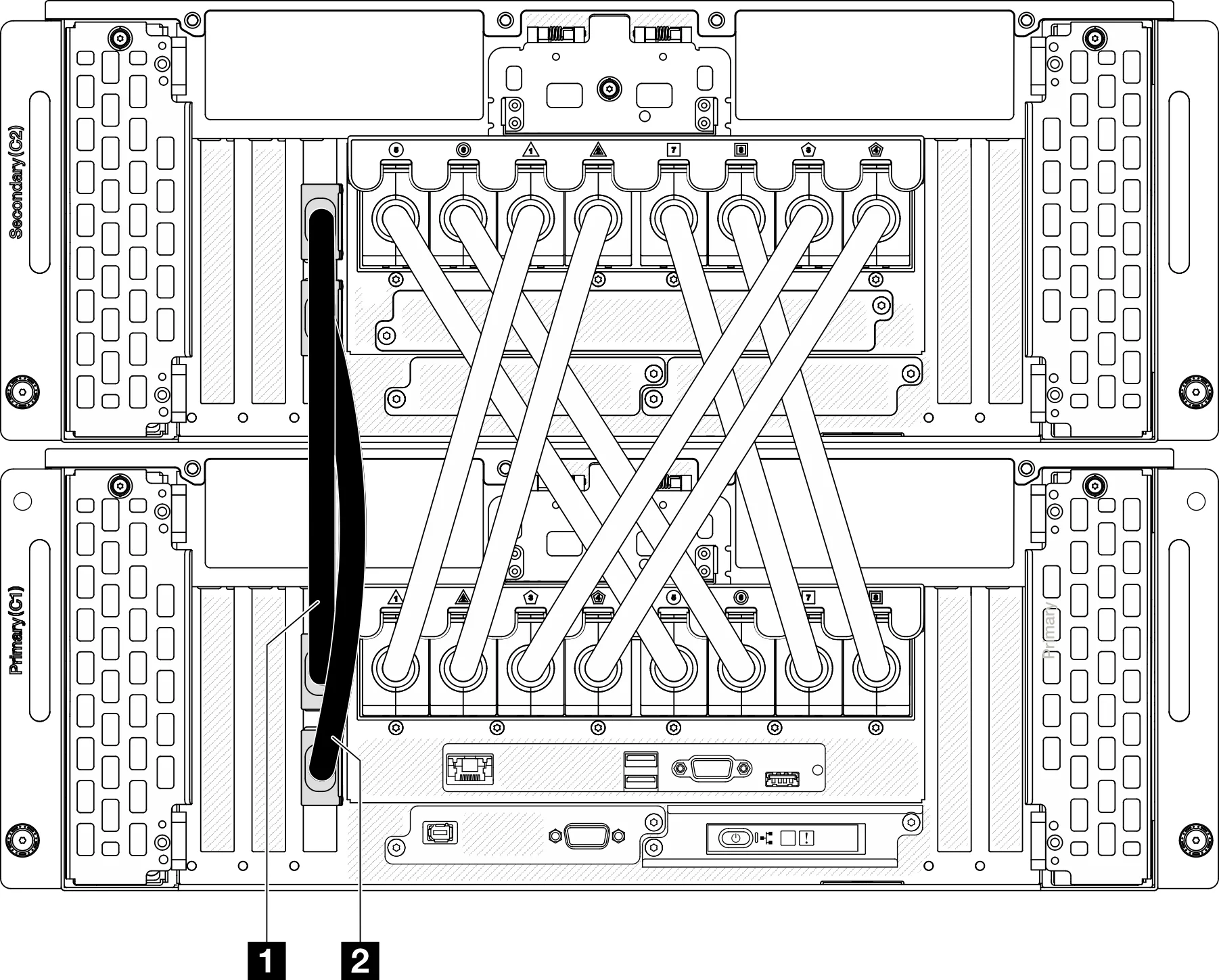
Open the UPI cover on the main chassis.

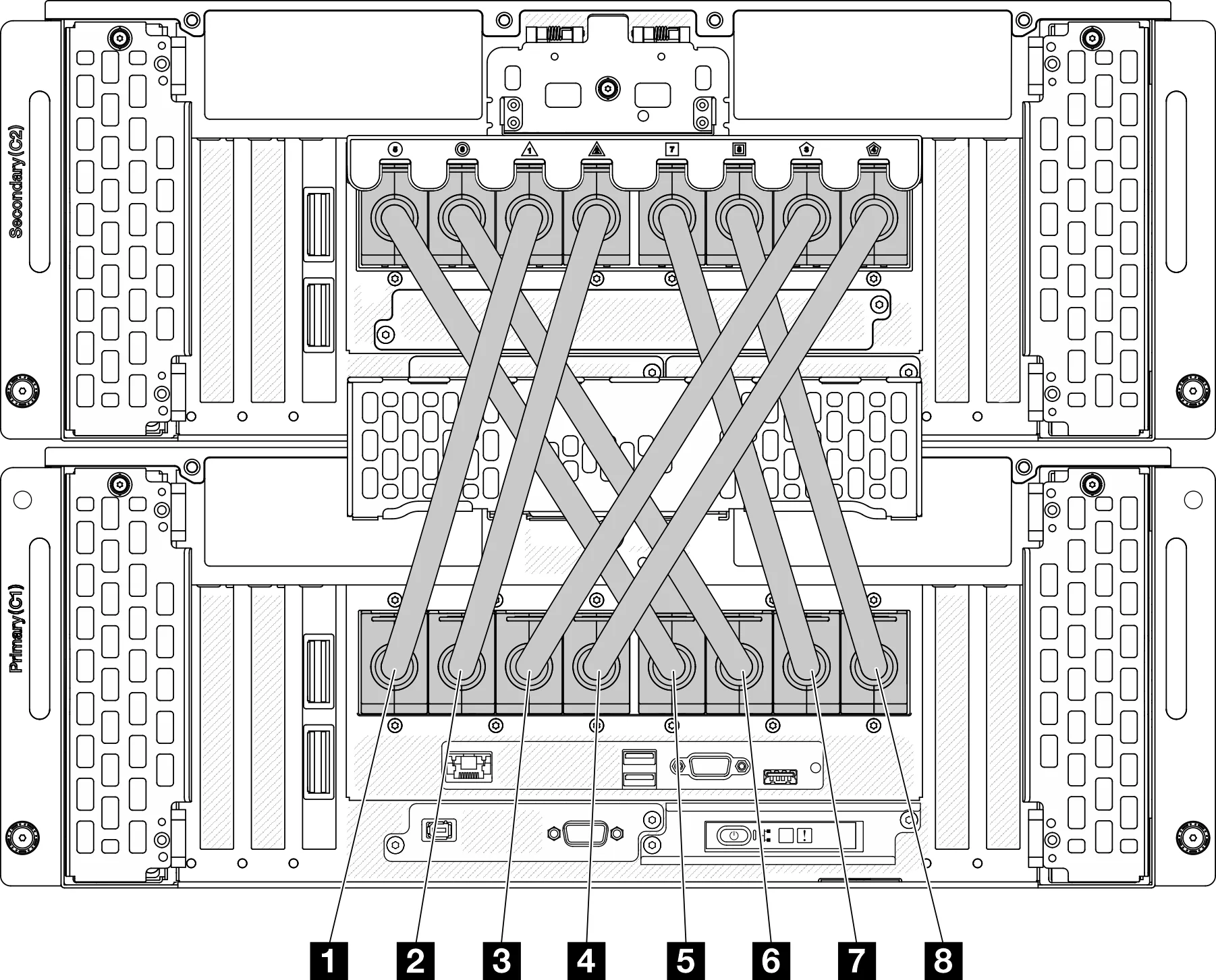
Removing the front UPI cables (8 pieces)
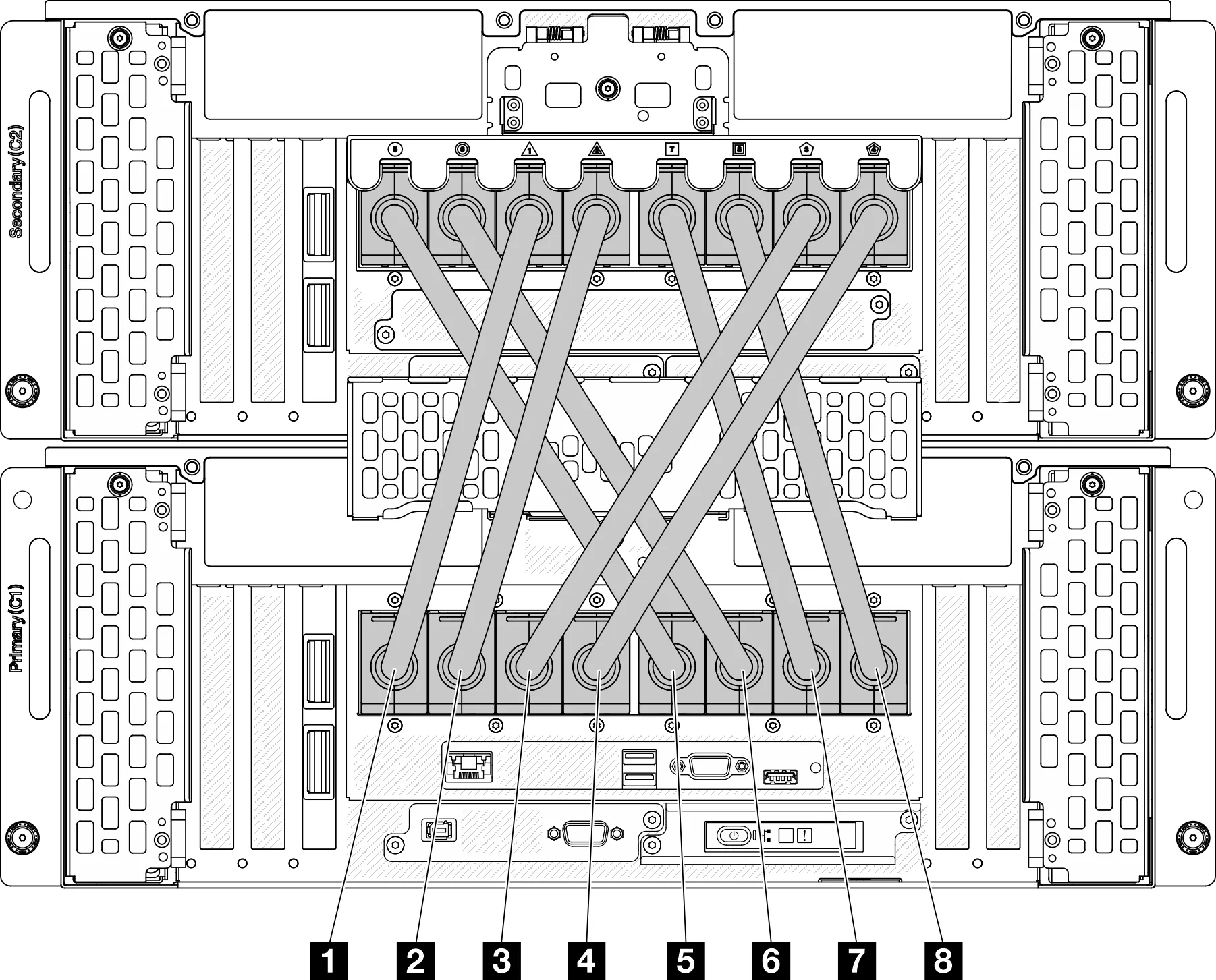
Make sure to remove all external cables in front and place all cables in order
Remove the main chassis
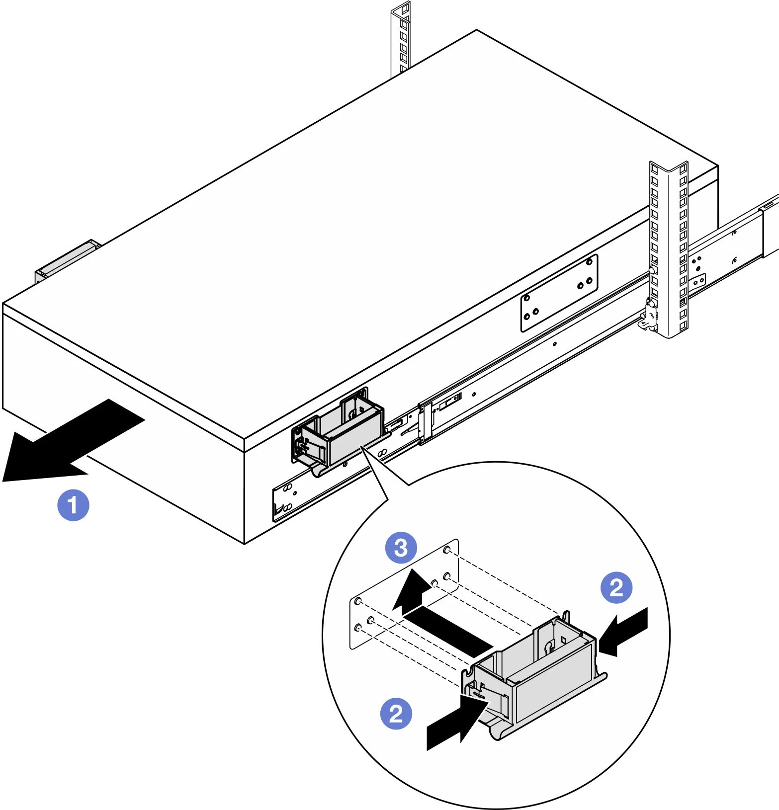
Install the front left and right auxiliary handles and slide the chassis to be fixed
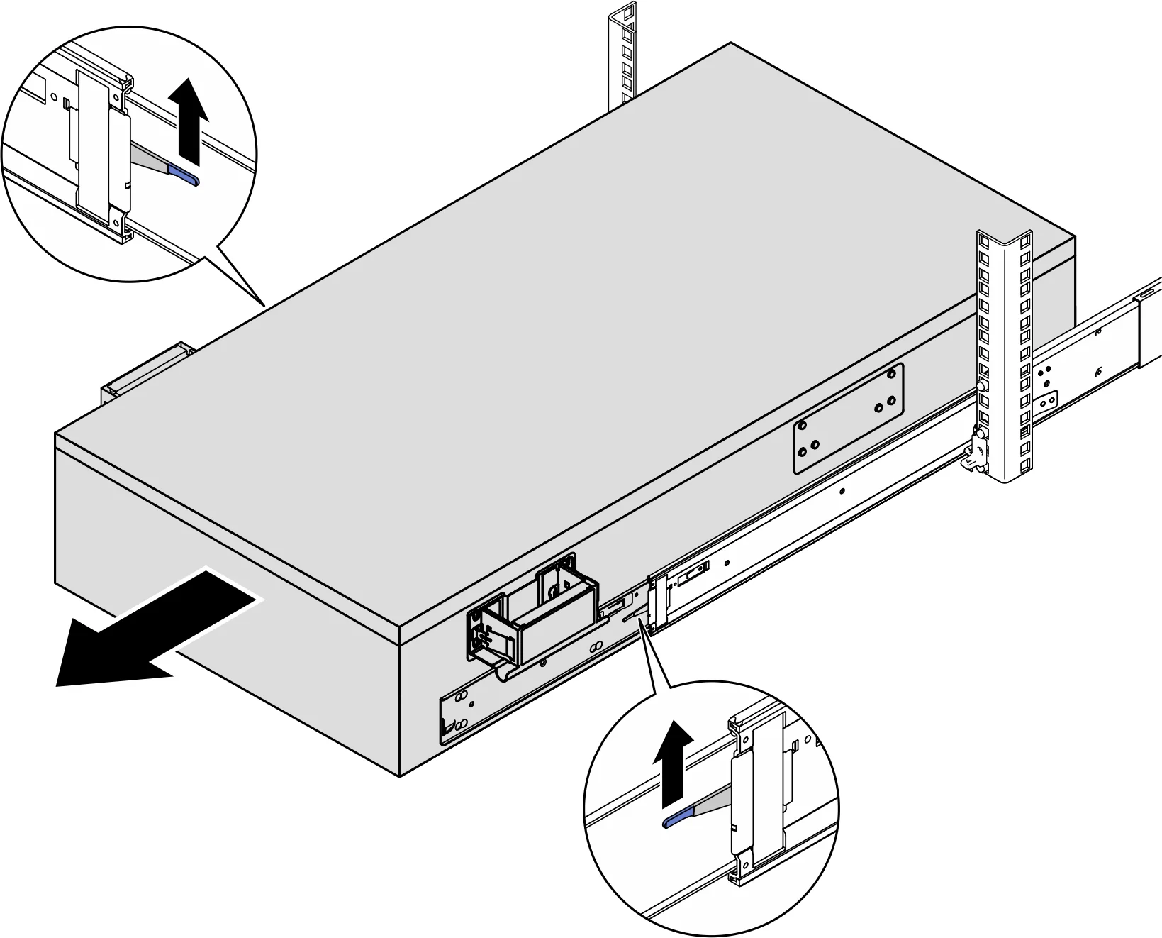
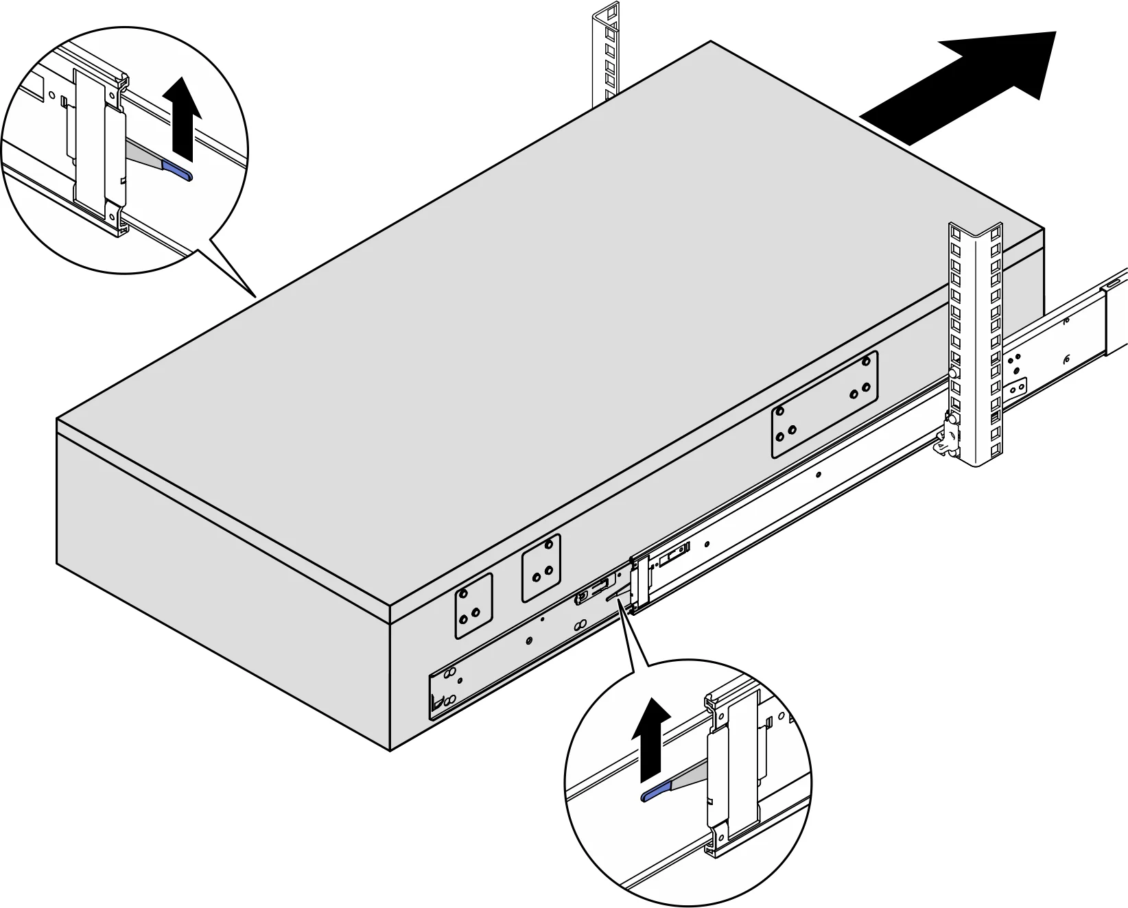
Lift the first pair of slide locks up to continue sliding out
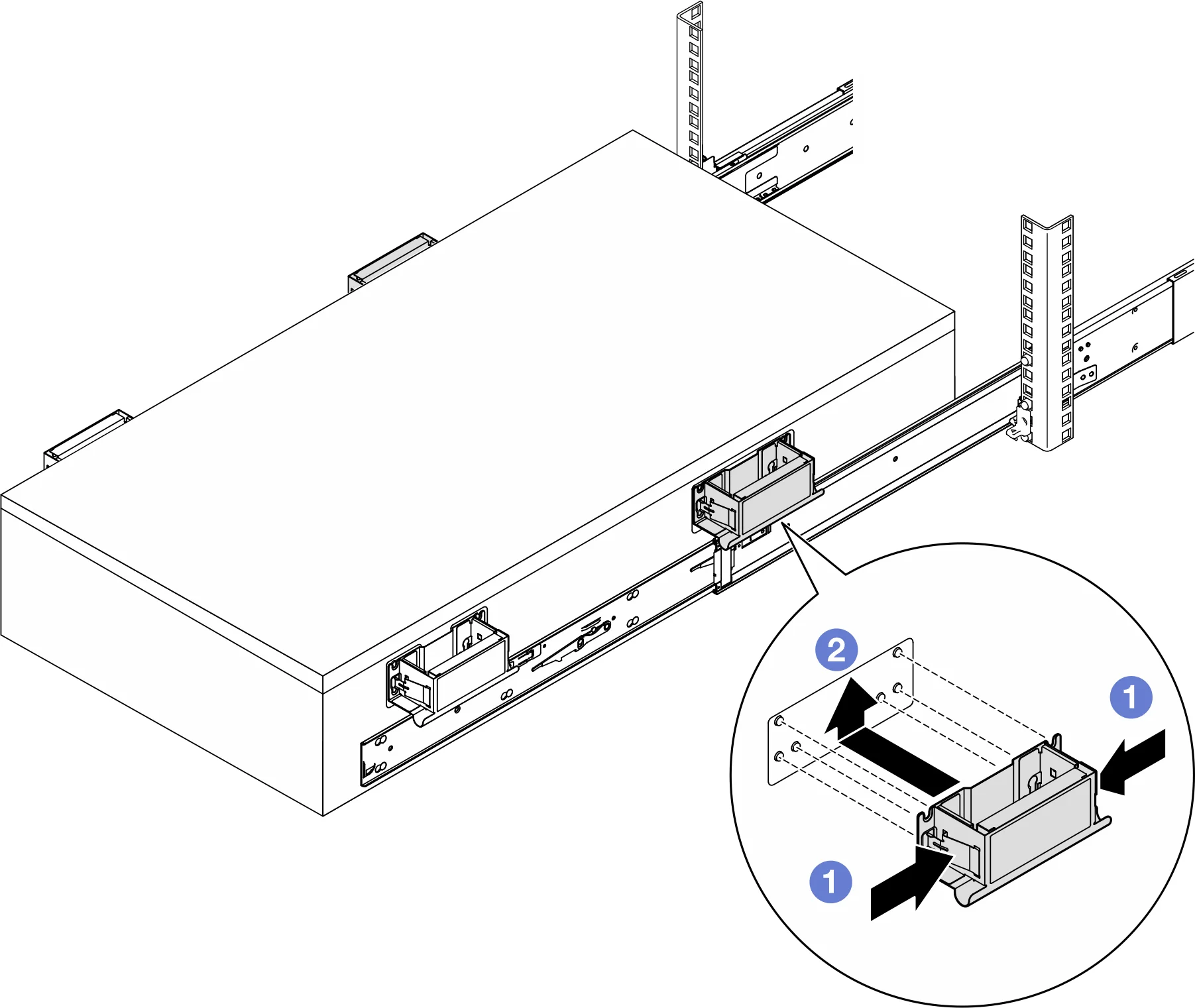
Install the rear two handles
lift the second slide lock to completely remove the server from the rack; Then place it on a level countertop
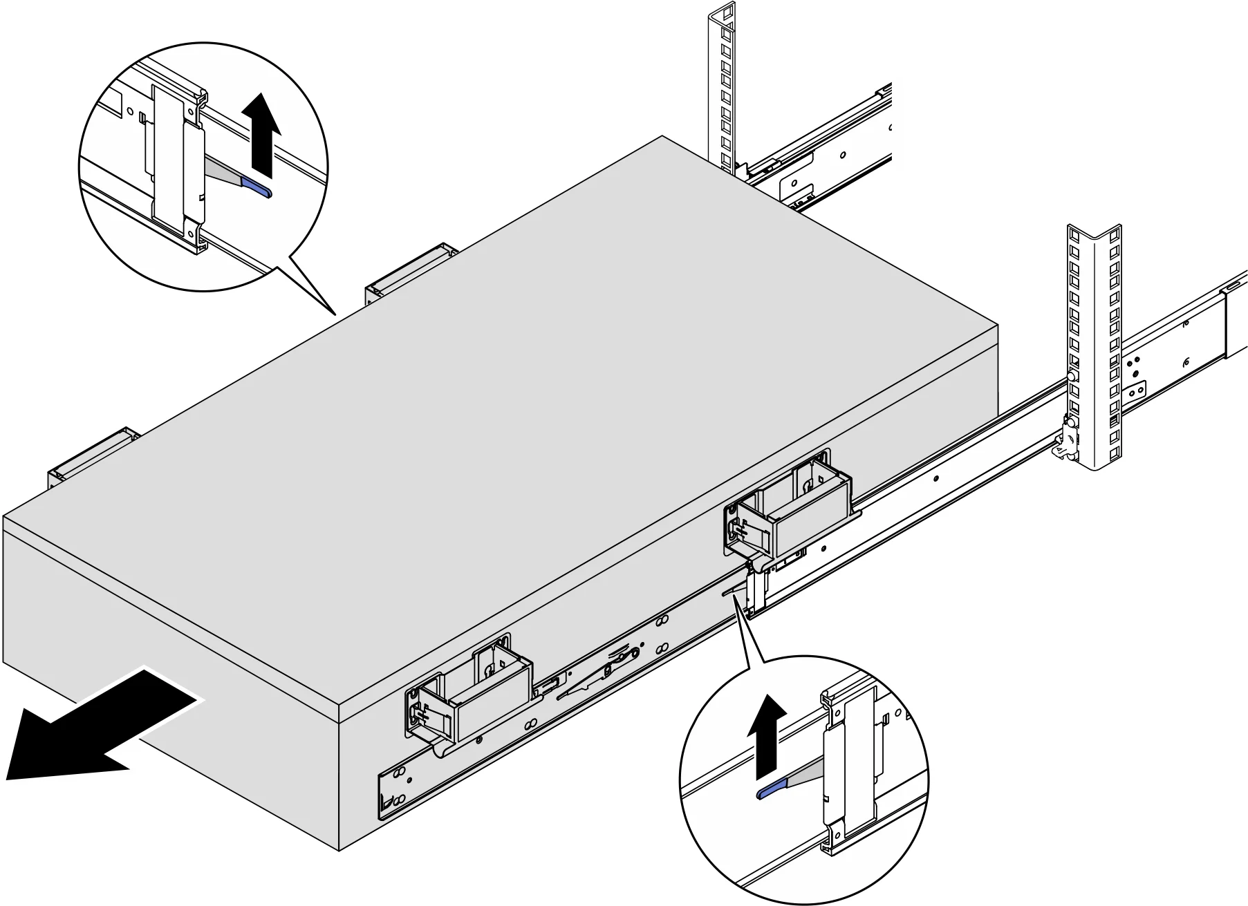
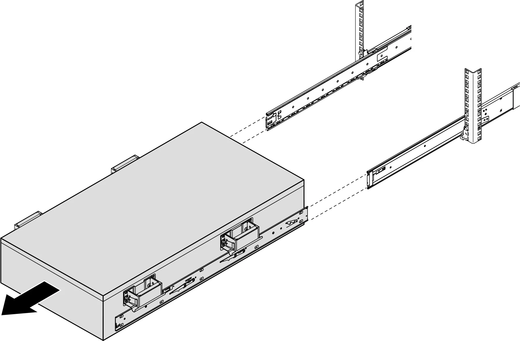
Remove the front top cover
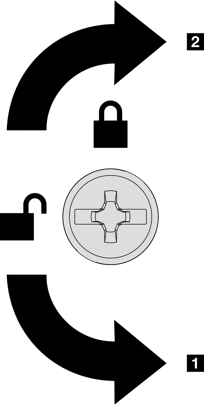
Use a screwdriver to unlock the top cover
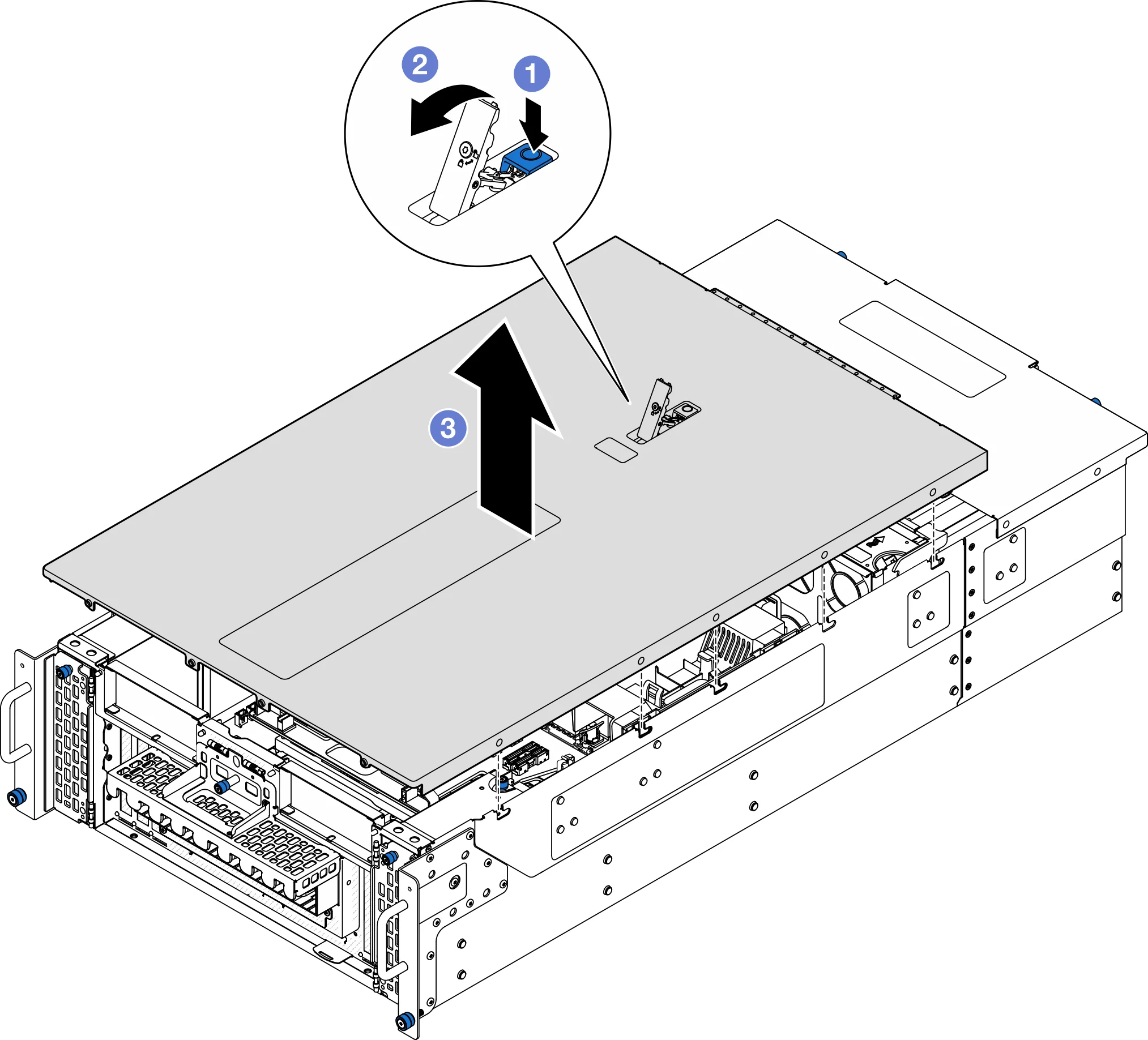
Remove the front top cover from the chassis
Remove the upper processor board (CPU board) air deflector
Unplug the cable from the M.2 boot adapter
- Loosen the screws on the signal cable.
- Tilt the interface and remove it.
- Unplug the power cord.
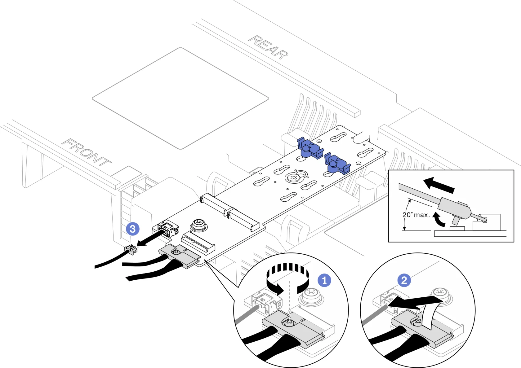
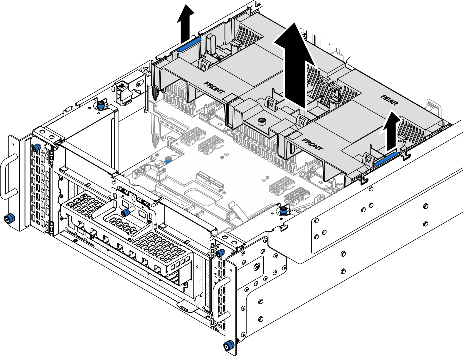
1. First, write down the cable connection method; Then, unplug and lift the cable that runs through the air deflector of the upper processor board (CPU board) and set it aside.
2. Grasp the two blue handles on the upper processor board (CPU board) air deflector and carefully remove the air deflector from the chassis.
Remove the CPU board
Unplug the UPI module cable from the upper processor board (CPU board).
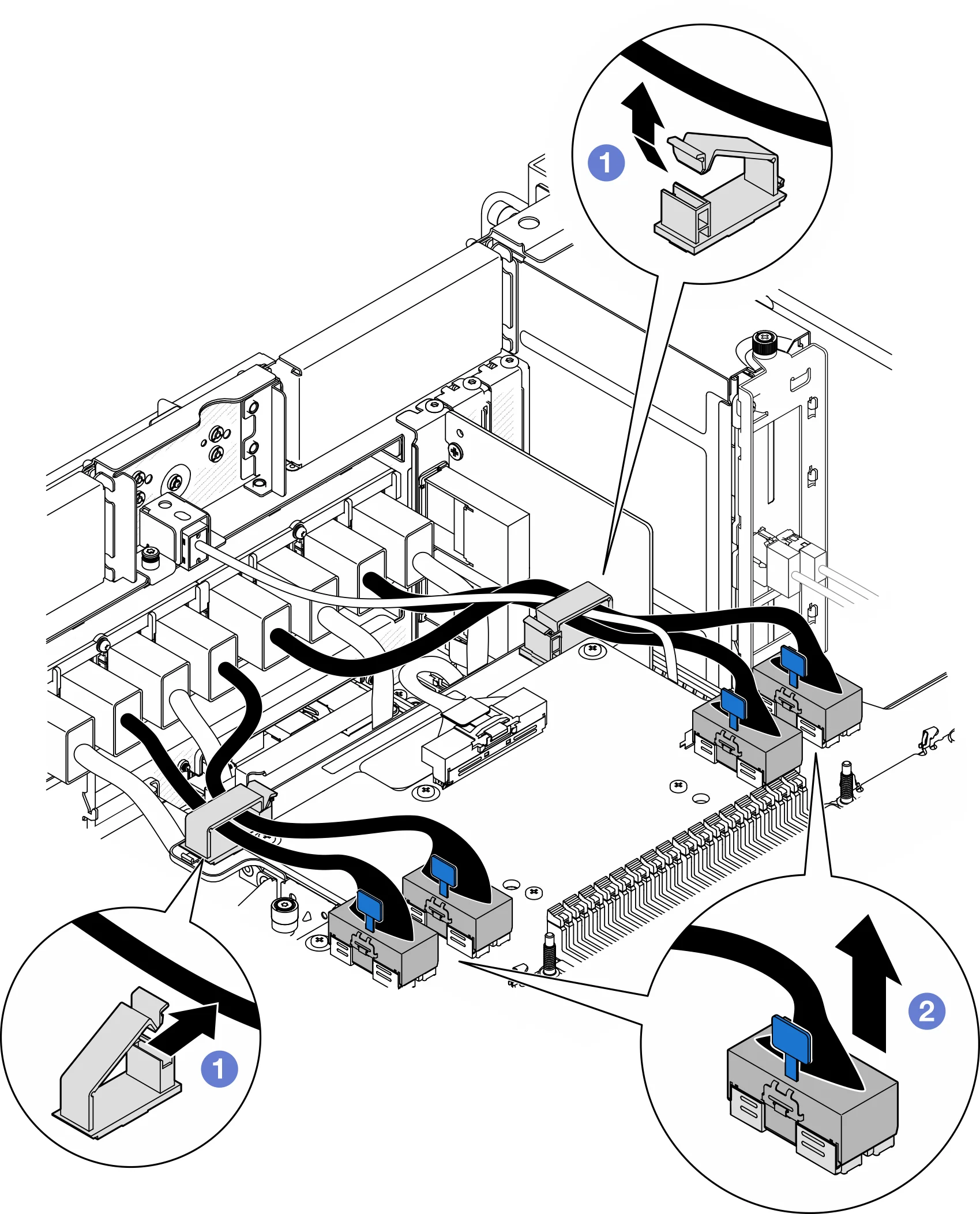
- Open the cable clamp and loosen the UPI module cable.
- Unplug the UPI module cable from the upper processor board (CPU board).
Unplug the internal sideband cables from the upper processor board (CPU board) and the lower processor board (motherboard).
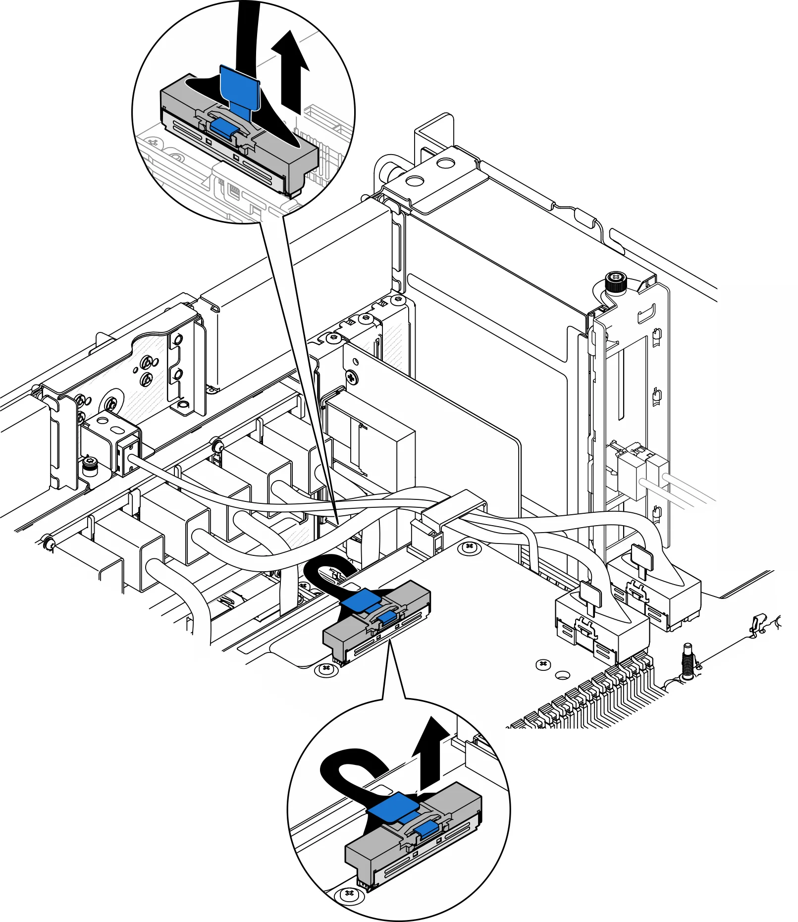
Unplug the internal UPI cable
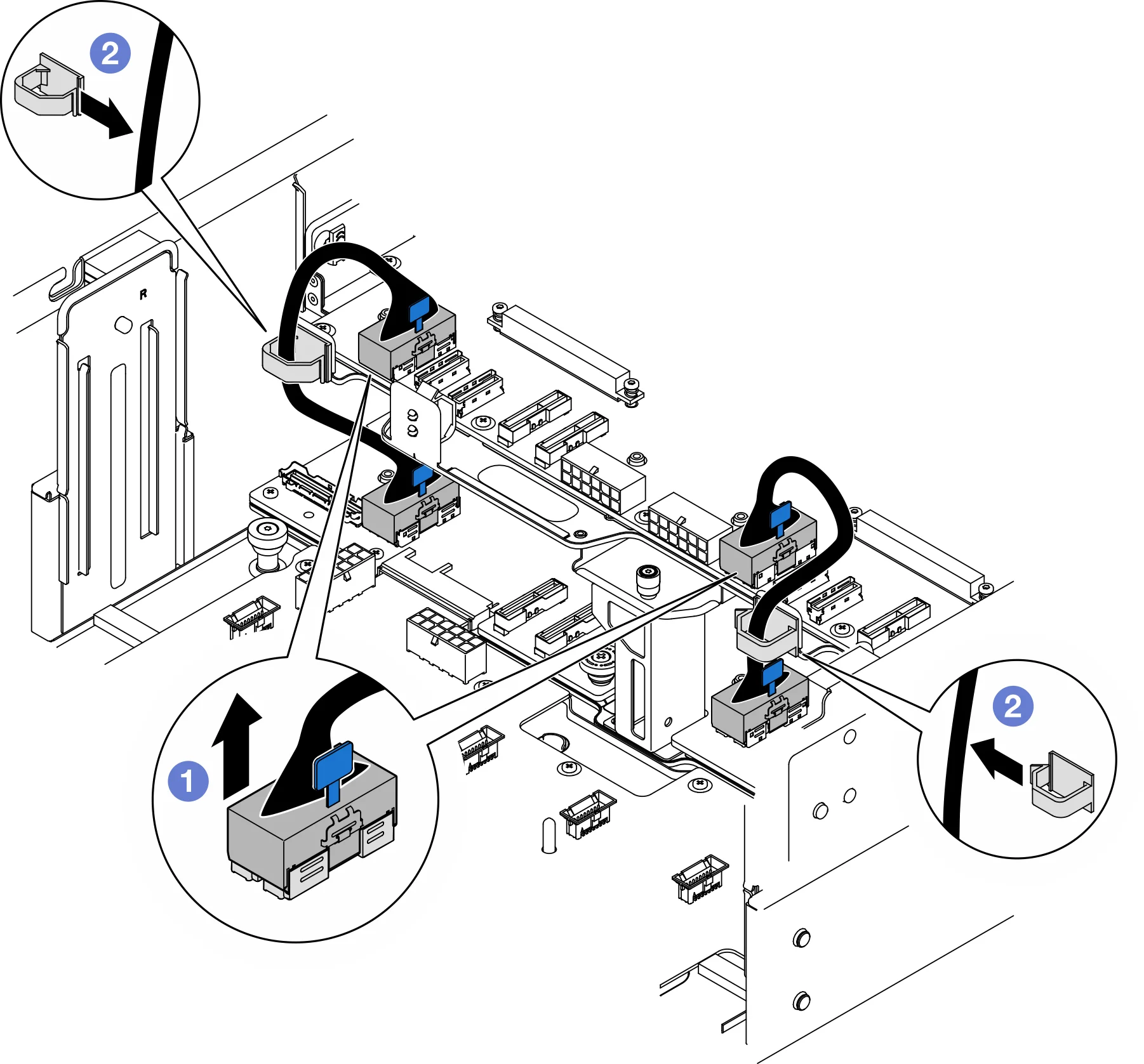
- Unplug the internal UPI cable from the upper processor board (CPU board).
- Remove the internal UPI cable from the cable clip.
Make an inventory of all remaining cables and record the interfaces to which the cables are connected; Then, unplug all remaining cables from the upper processor board (CPU board) to ensure a wireless cable connection
Loosen the upper processor board (CPU board)
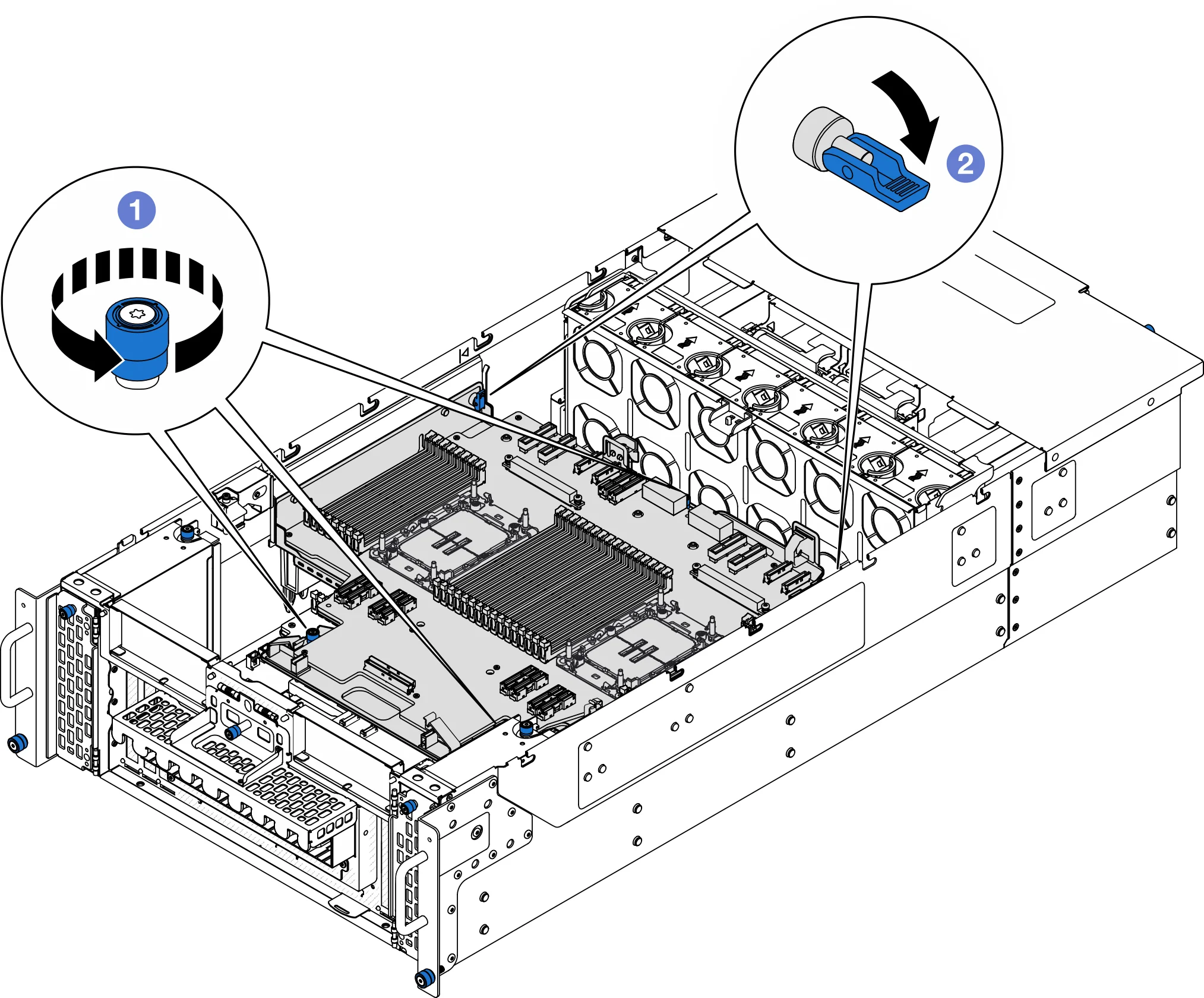
- Loosen the three thumbscrews. Use a screwdriver if needed.
- Open the plunger to the unlocked position.
Grasp the blue handle and remove the upper processor board (CPU board)
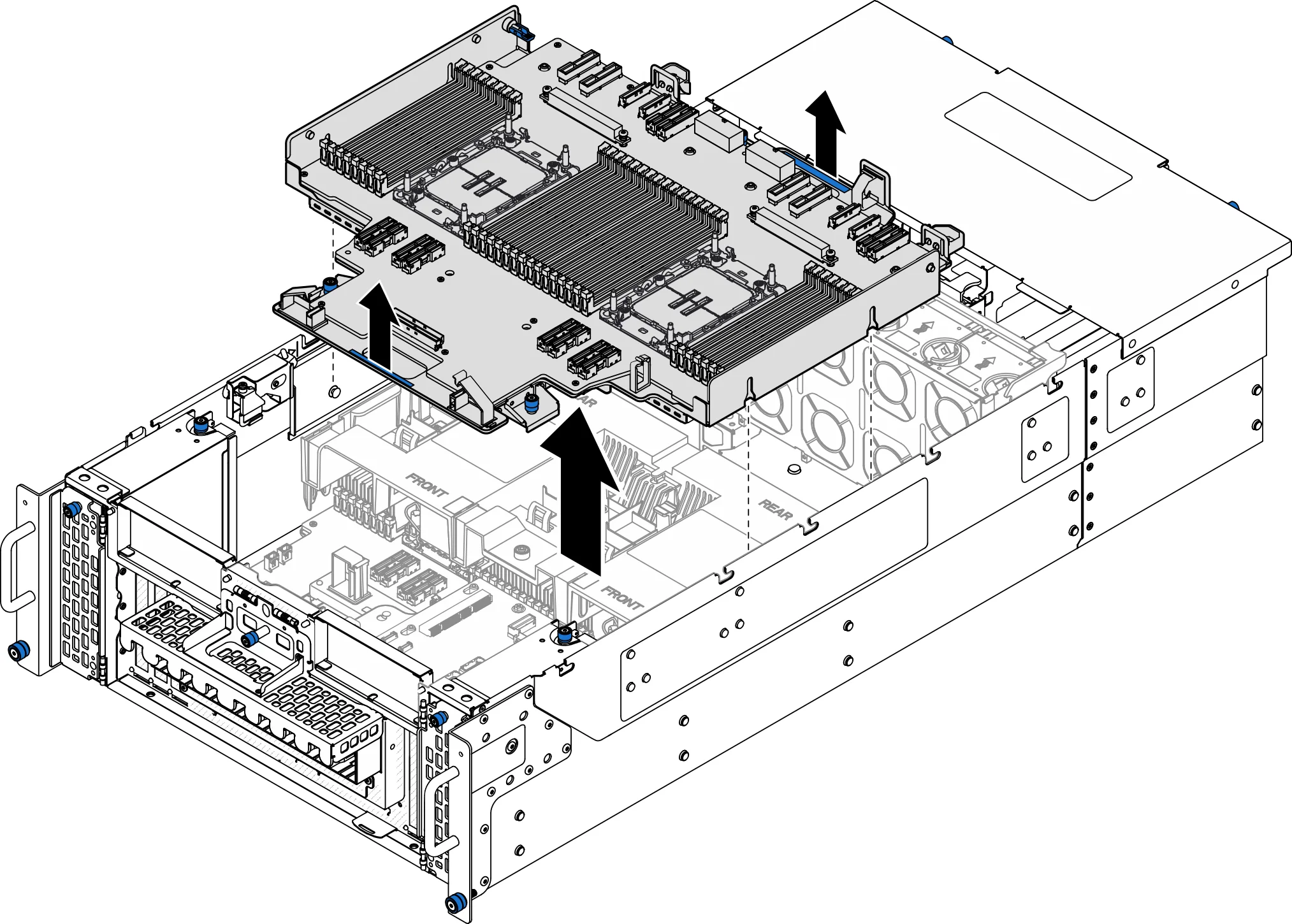
Properly position the CPU board to a flat surface
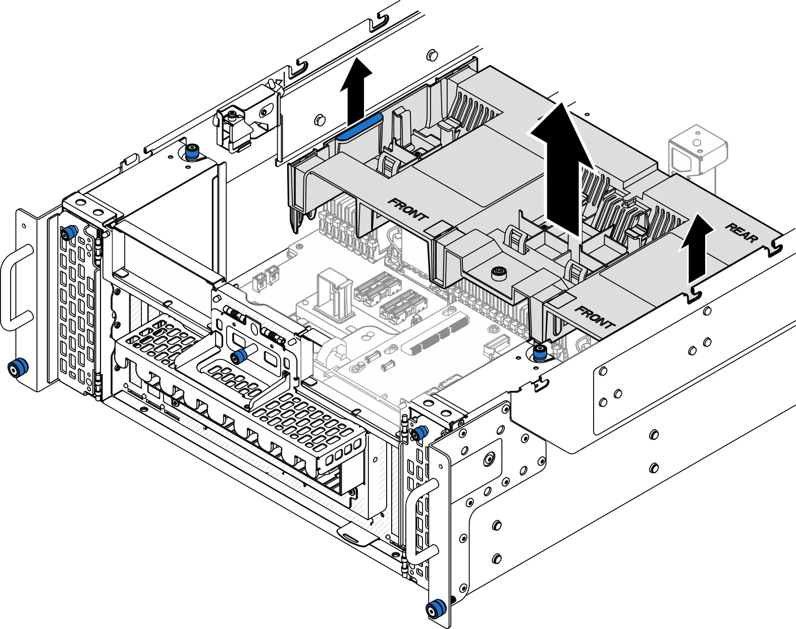
Remove the lower processor board (motherboard) air deflector
First, note the cable connection method; Then, unplug the cable that runs through the air deflector of the processor board (motherboard) below and remove it aside.
Grab the two blue handles on the air deflector of the lower processor board (motherboard) and carefully remove them from the chassis.
Install memory
Schematic diagram of the motherboard interface
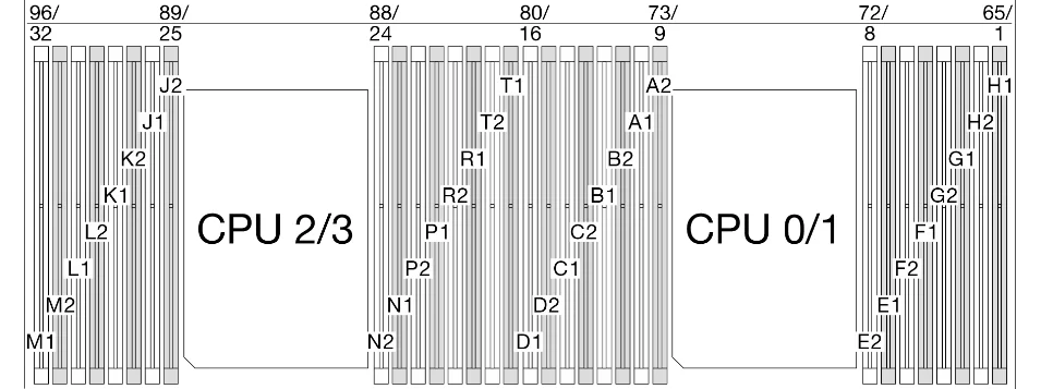
Schematic diagram of CPU board interface

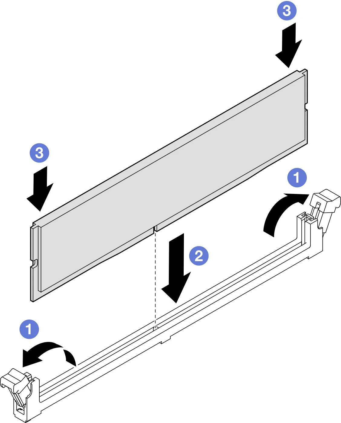
Check the serial number and install the memory according to the installation instructions in the table, and confirm that the memory is installed in place, the lock is normal, and the memory slot is installed correctly.
Install the lower processor board (motherboard) air deflector
Grab the two blue handles and align the lower processor board (motherboard) air guide tabs with the slots on either side of the chassis; Then, place the lower processor board (motherboard) air deflector into the chassis.
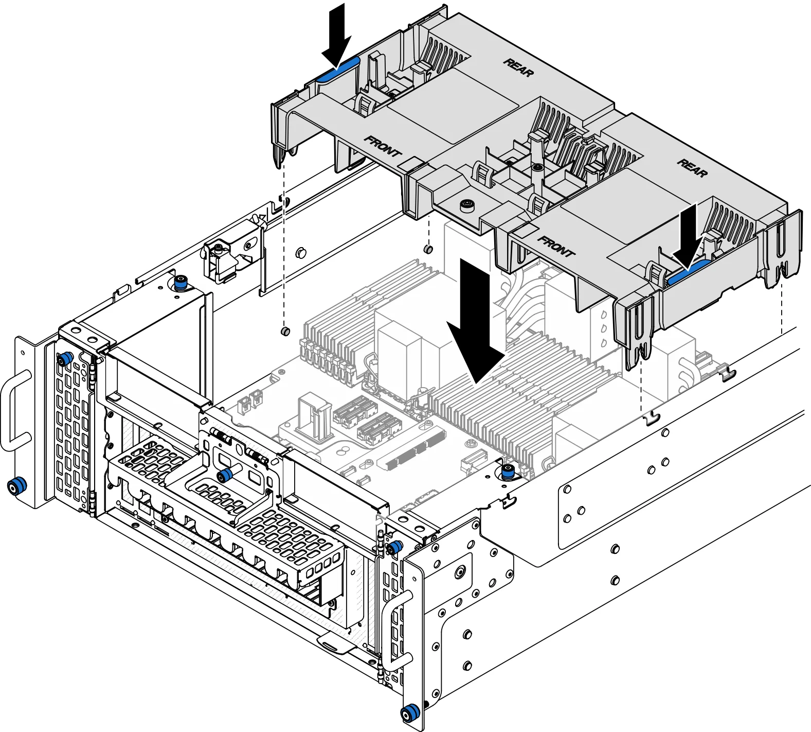
- Tap down on the lower processor board (motherboard) air deflector until it is firmly in place.
- Attach all previously unplugged cables and thread them through the air deflector of the processor board (motherboard) below.
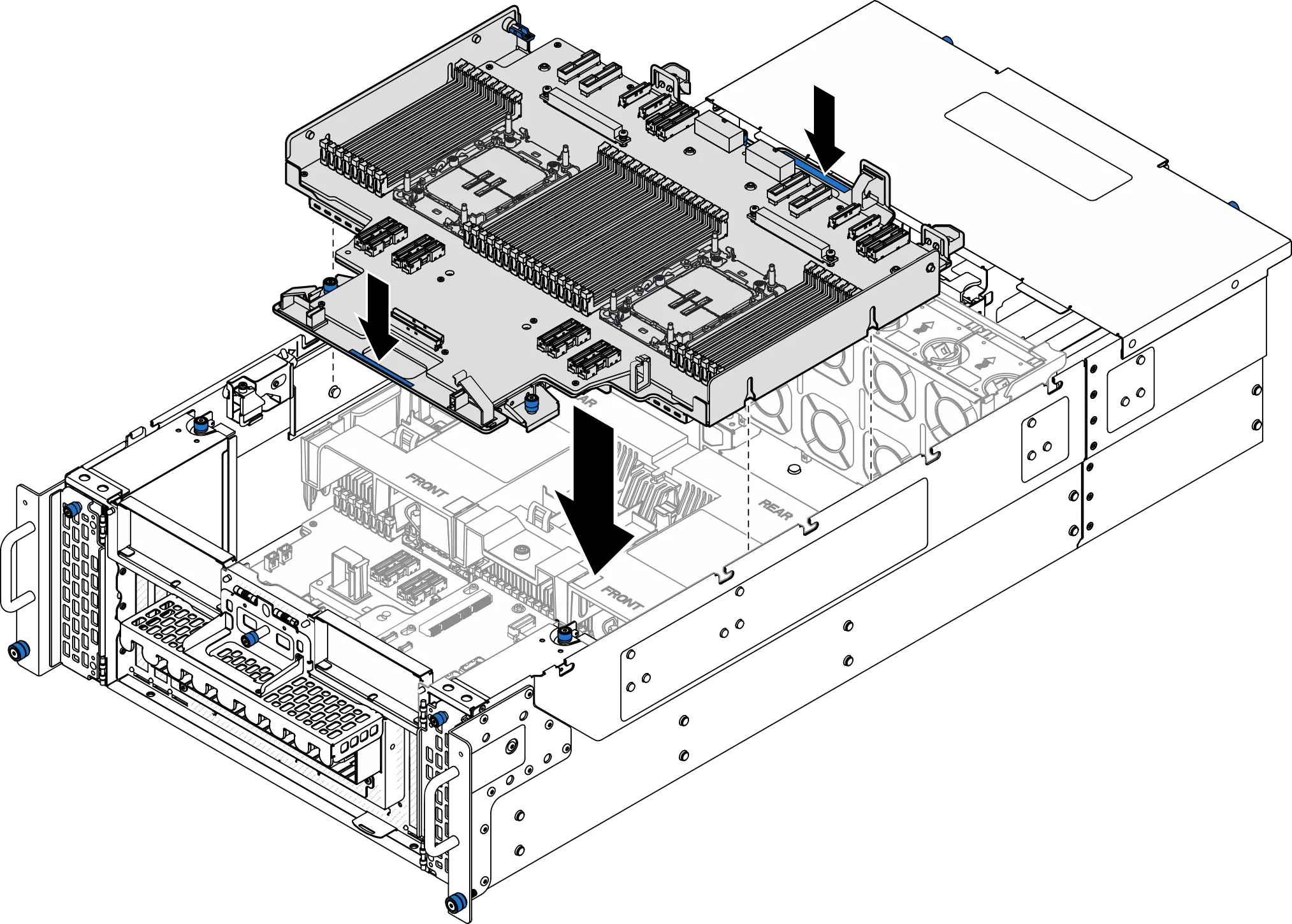
Installing the upper processor board (CPU board)
Grasp the blue handle and place the upper processor board (CPU board) down into the chassis until the T-pins inside the chassis engage with the upper processor board (CPU board).
Fixing the upper processor board (CPU board)
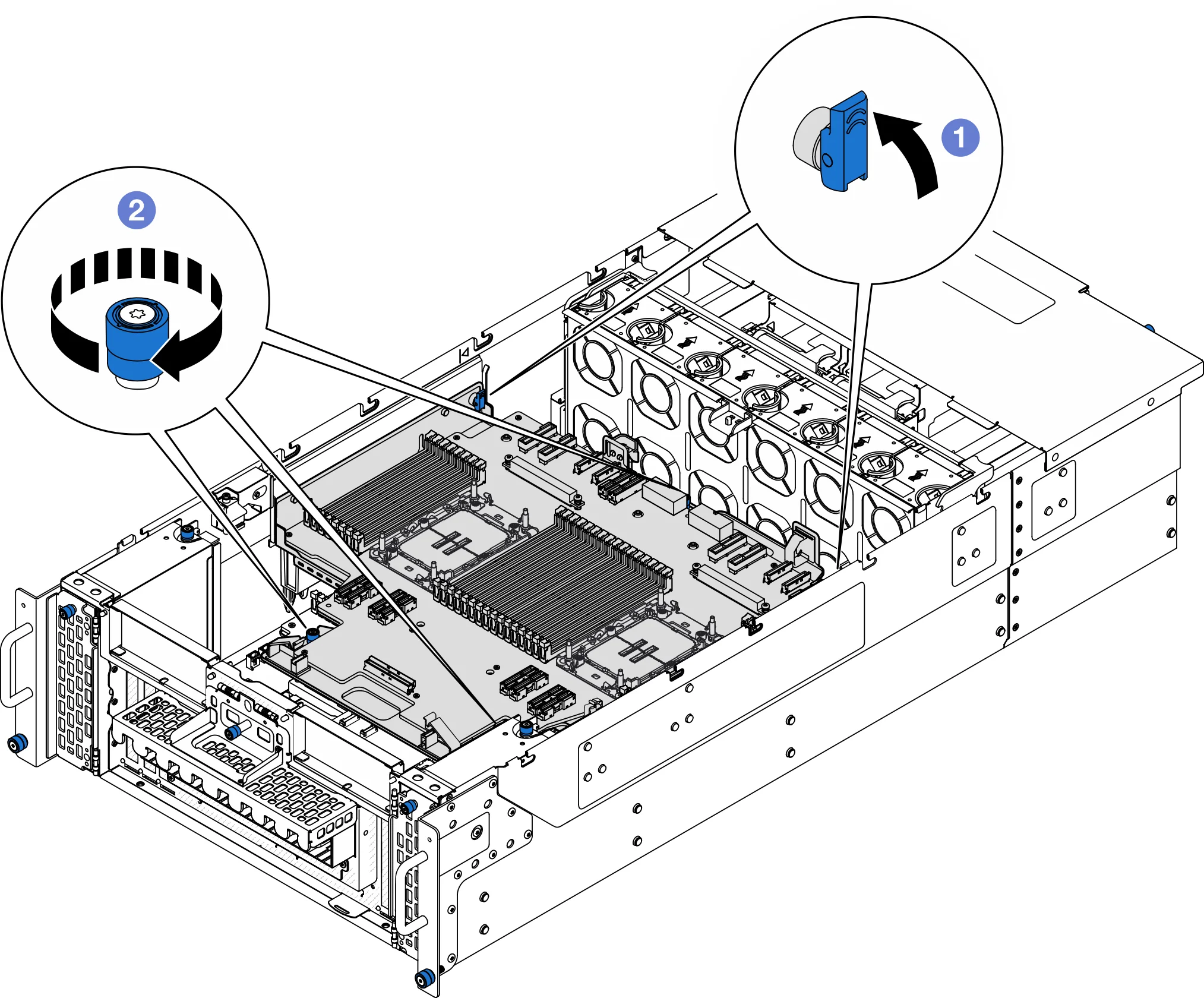
- Close the plunger to the locked position.
- Tighten the three thumbscrews. Use a screwdriver if needed.
Connect the power cord to the upper processor board (CPU board)
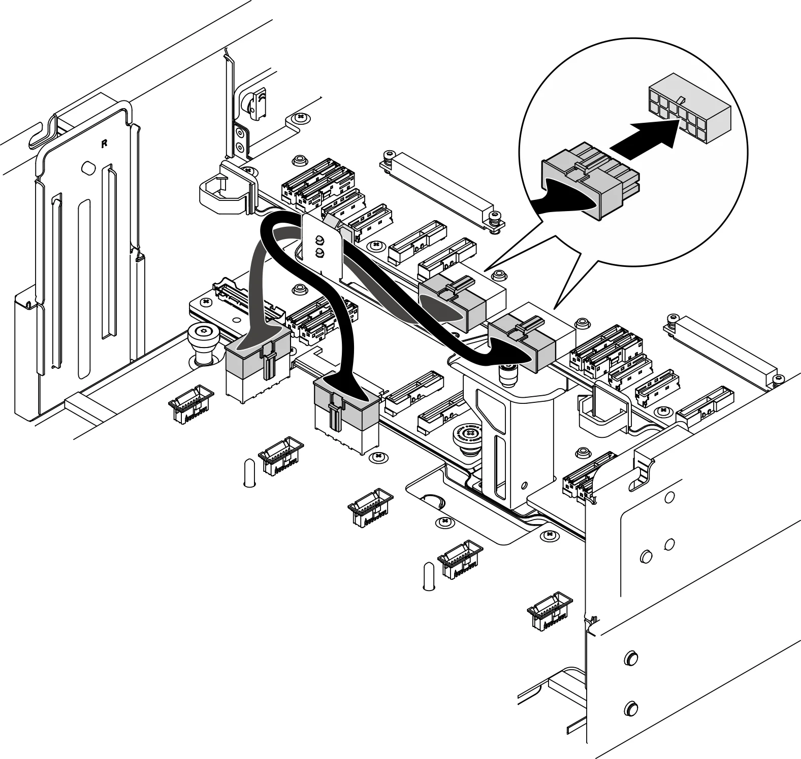
Connect the internal UPI cable
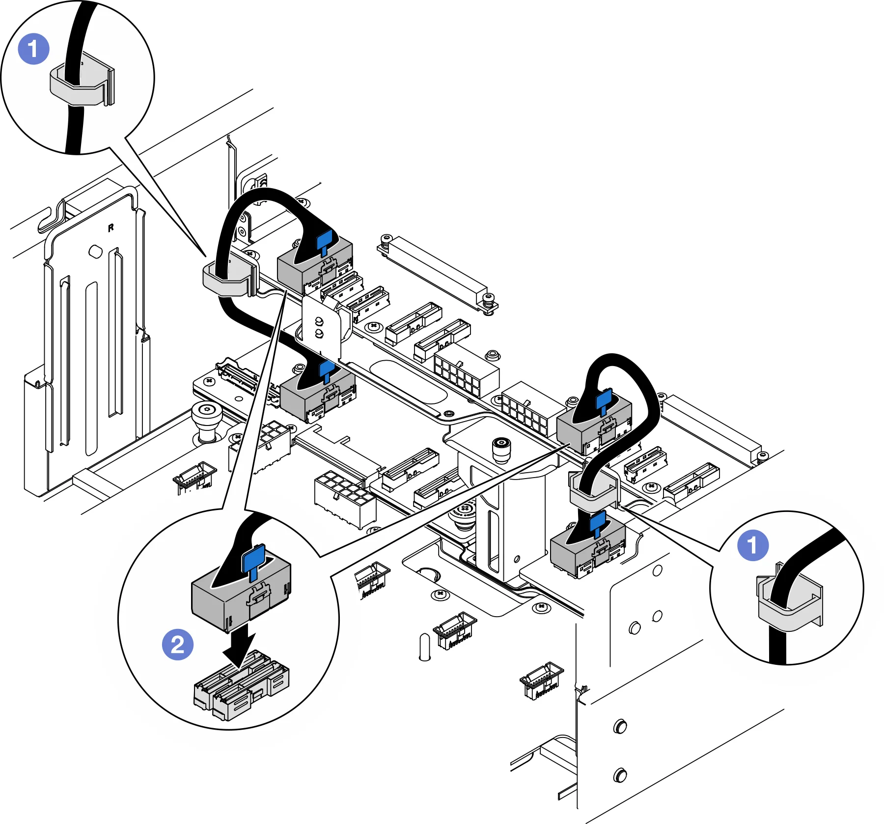
- Thread the internal UPI cable through the cable clip.
- Connect the internal UPI cable to the upper processor board (CPU board)
Connect the internal sideband cable to the upper processor board (CPU board) and the lower processor board (motherboard)
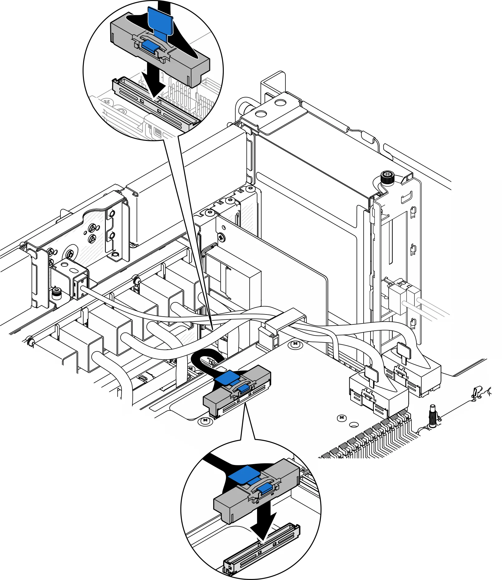
Connect the UPI module cables
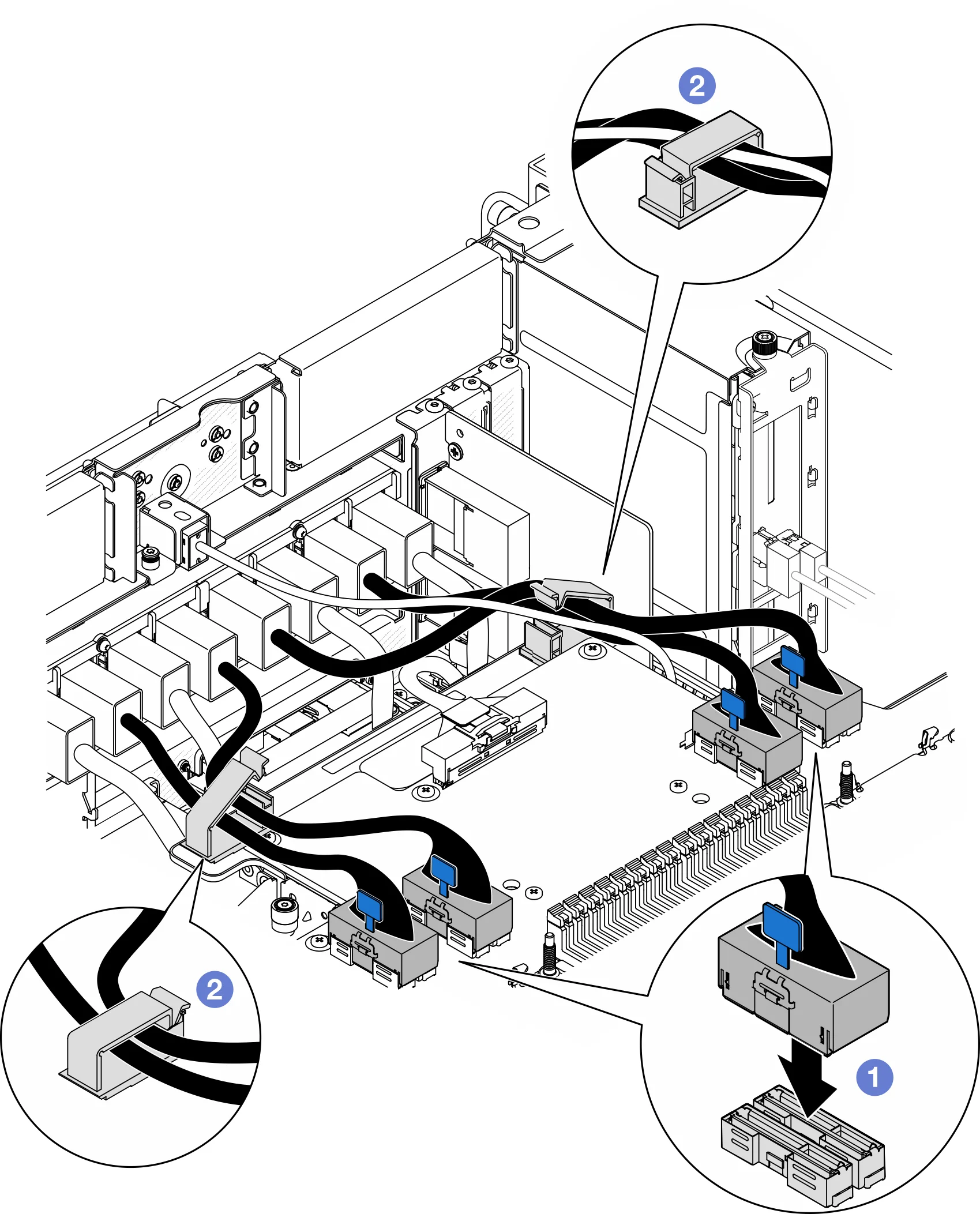
- Connect the UPI module cable to the upper processor board (CPU board).
- Thread the UPI module cable through the cable clamp and close the cable clamp.
Retrieve all previously unplugged cables. Confirm that the memory of the CPU board is installed in place, and the installation slots are consistent with the table.
Install the upper processor board (CPU board) air deflector
Grab the two blue handles and align the upper processor board (CPU board) air deflector tabs with the slots on either side of the chassis; Then, place the upper processor board (CPU board) air deflector into the chassis
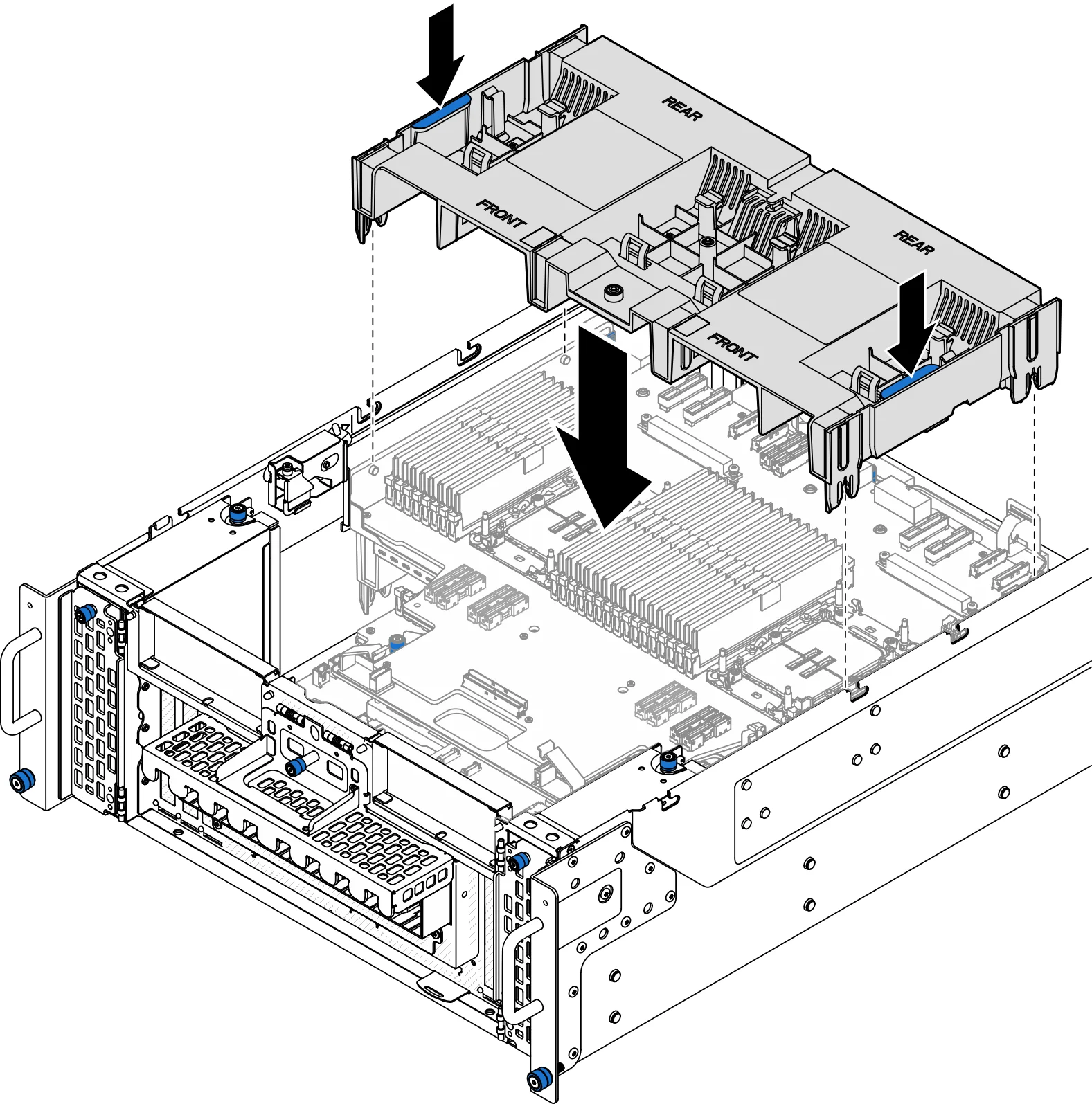
- Tap down on the upper processor board (CPU board) air defour until it is firmly in place.
- Attach all previously unplugged cables through the air deflector of the upper processor board (CPU board).
- Connect the cable to the M.2 boot adapter.
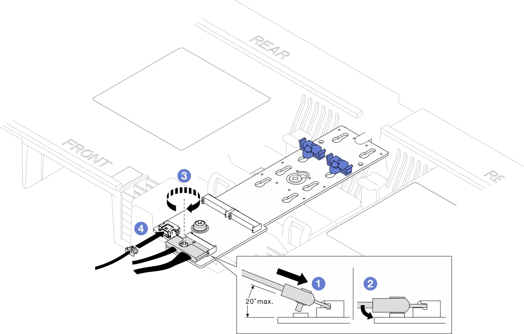
- Tilt the interface at least 20 degrees and insert it until the bottom surface touches the bevel.
- Flatten the interface down.
- Tighten the screws on the signal cable.
- Power cord to connect to the M.2 boot adapter (4).
Install the front top cover
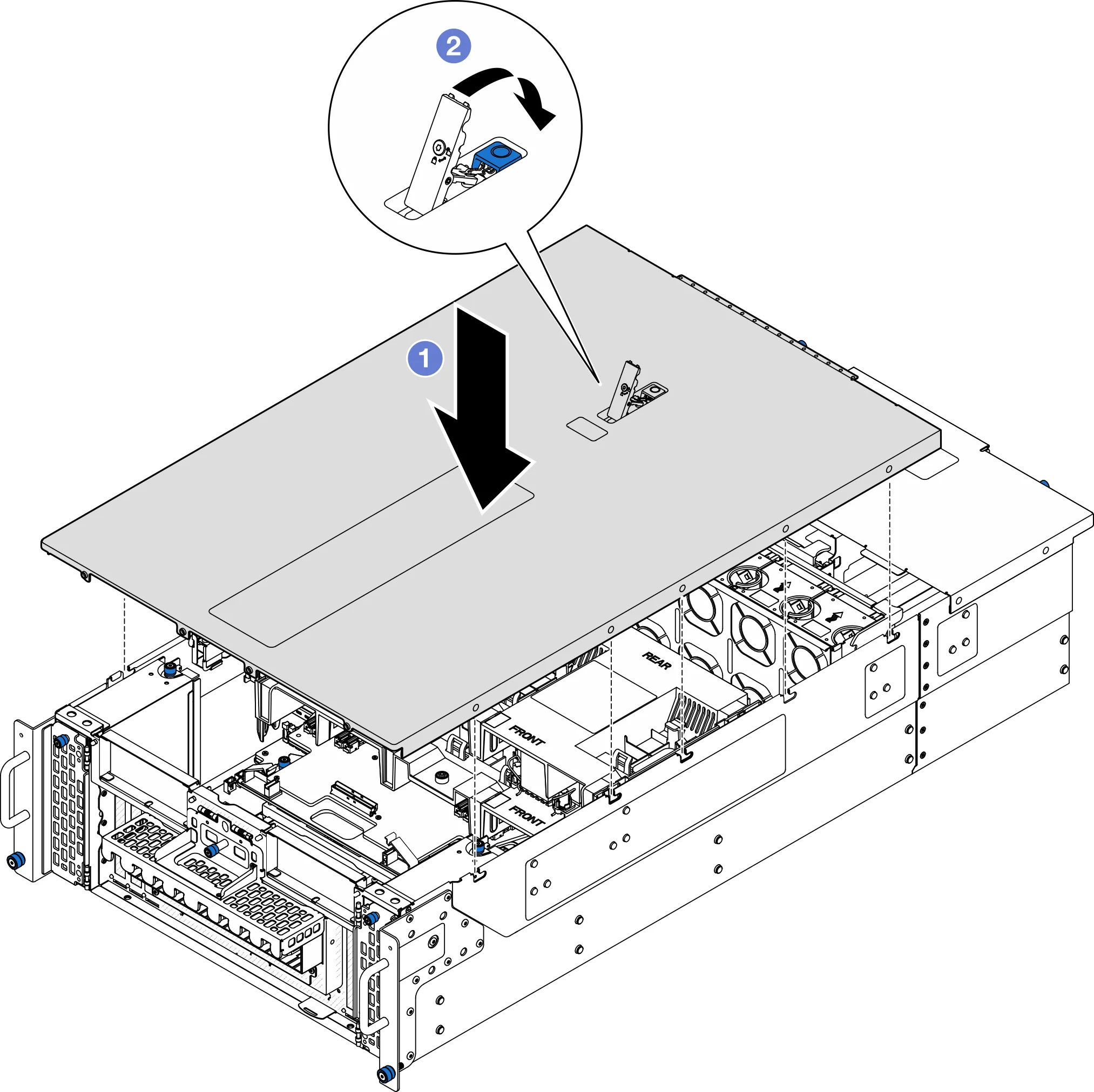
- Align the front top cover guide pins with the guide holes on the chassis; then, place the front top cover on top of the chassis and align both sides.
- Rotate the slidelock down until it cannot be rotated
Mount the server into the rail
Mounting handle
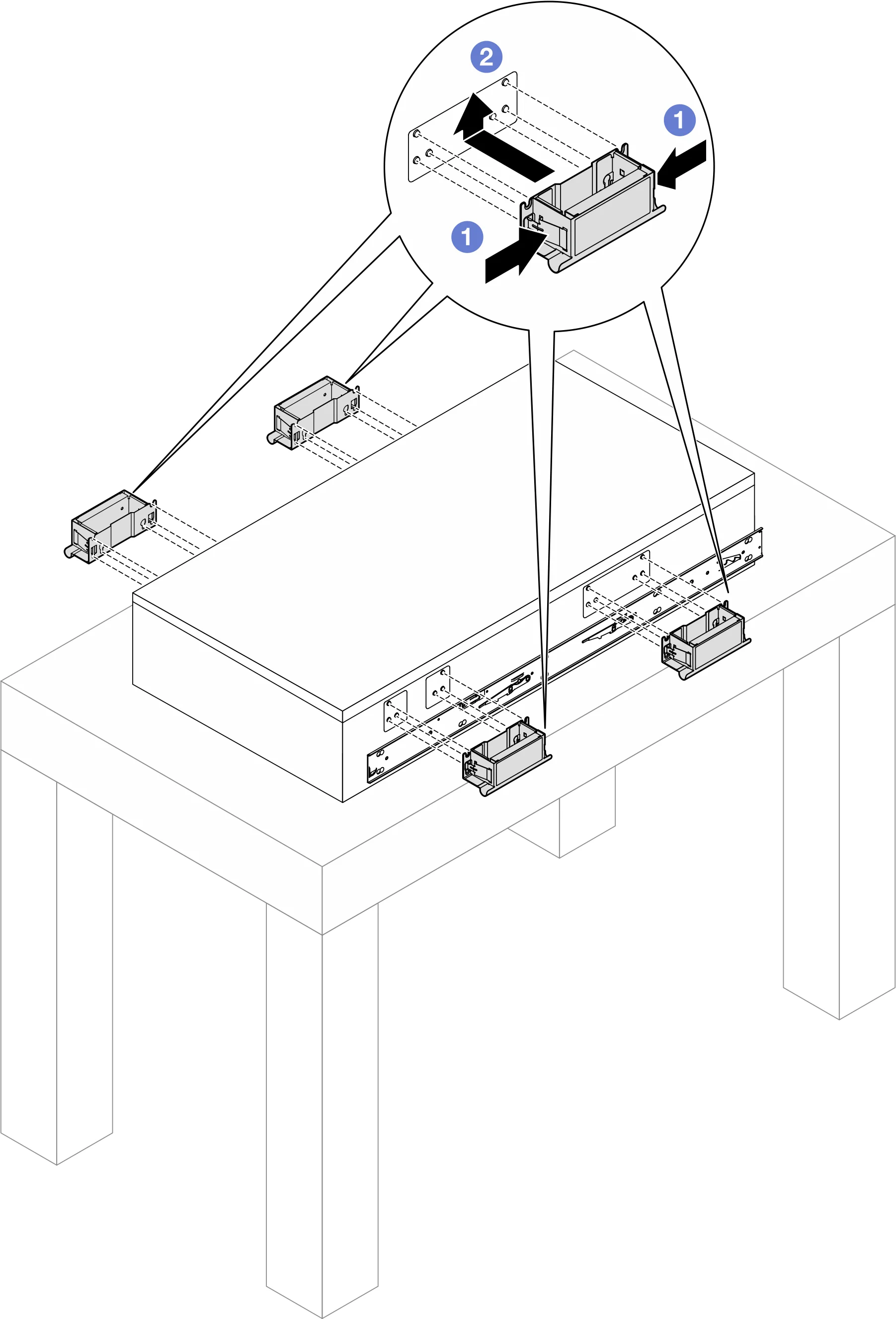
Mount the server to the rack.
|
| note When moving a server, always grasp the server's lift point or lift handle. |
| note Before inserting the inside rail into the middle rail, make sure the ball holder is at the very front of the middle rail. | |
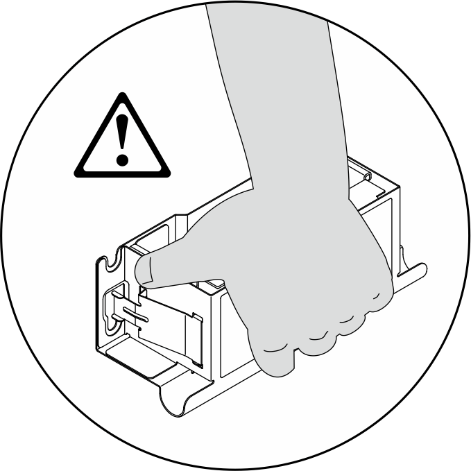
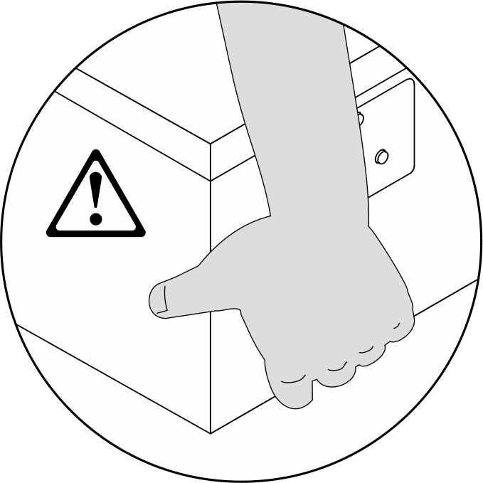
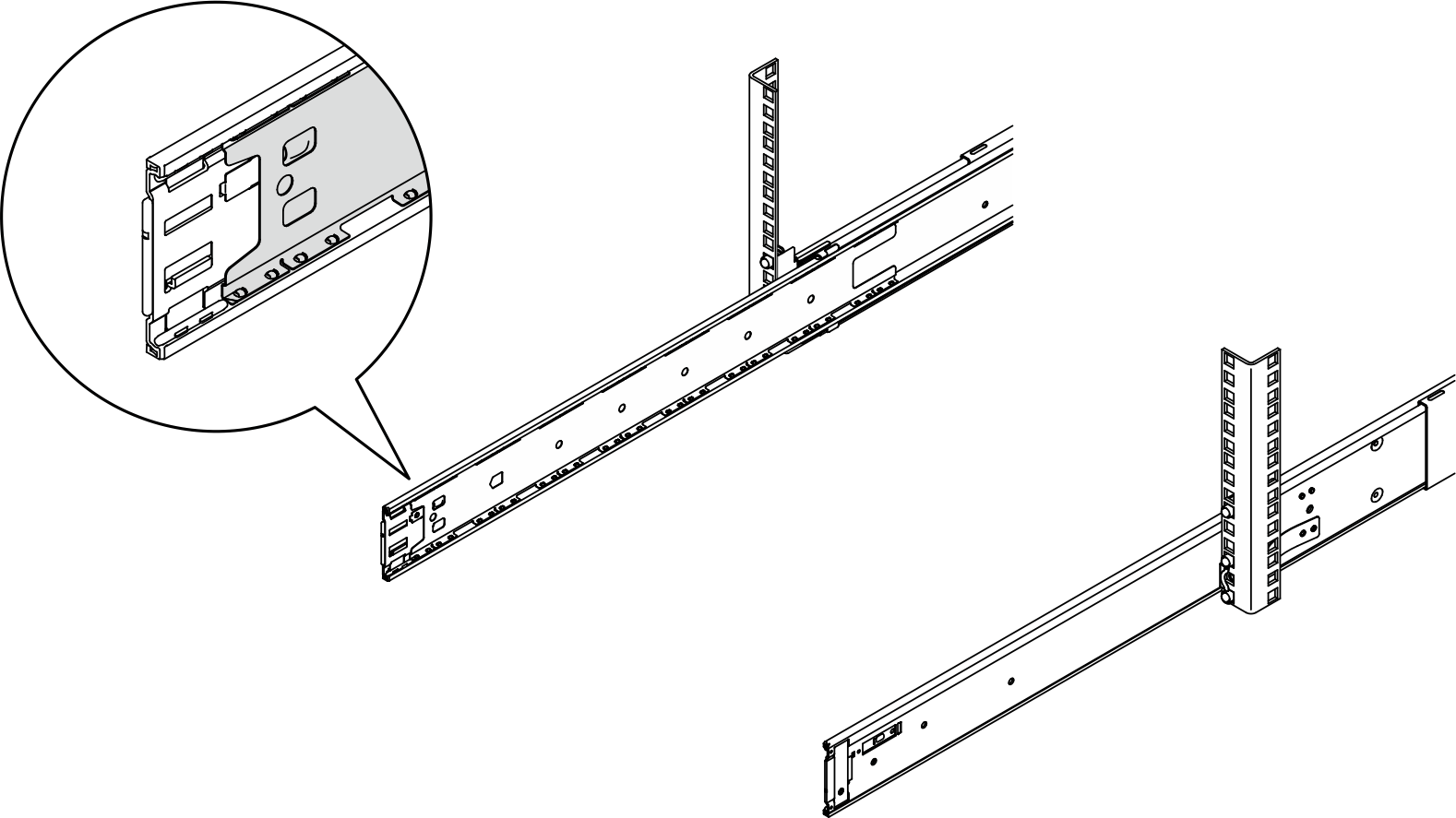
Align the two rear ends of the inside rail with the opening on the middle rail and ensure that the two pairs of rails are properly mated. Then, carefully slide the server into the rack until the rails "click" into place.
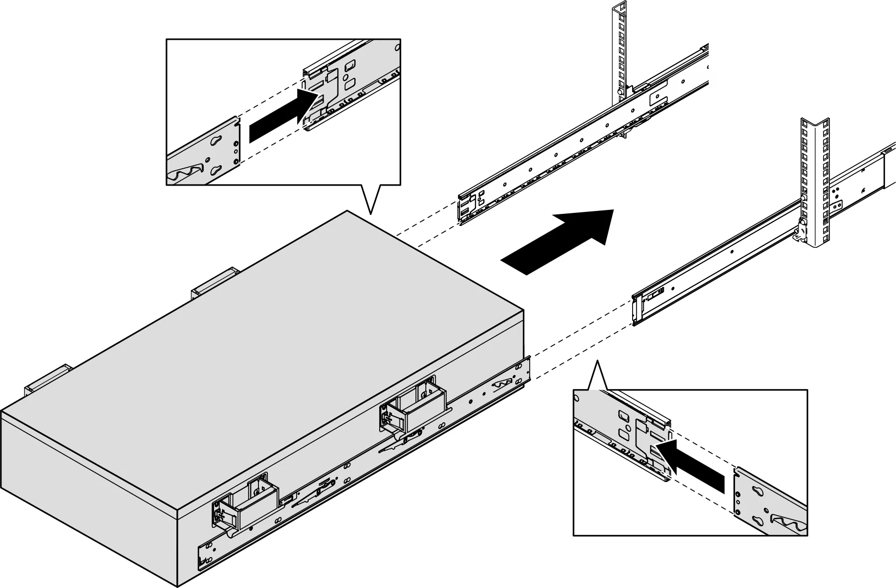
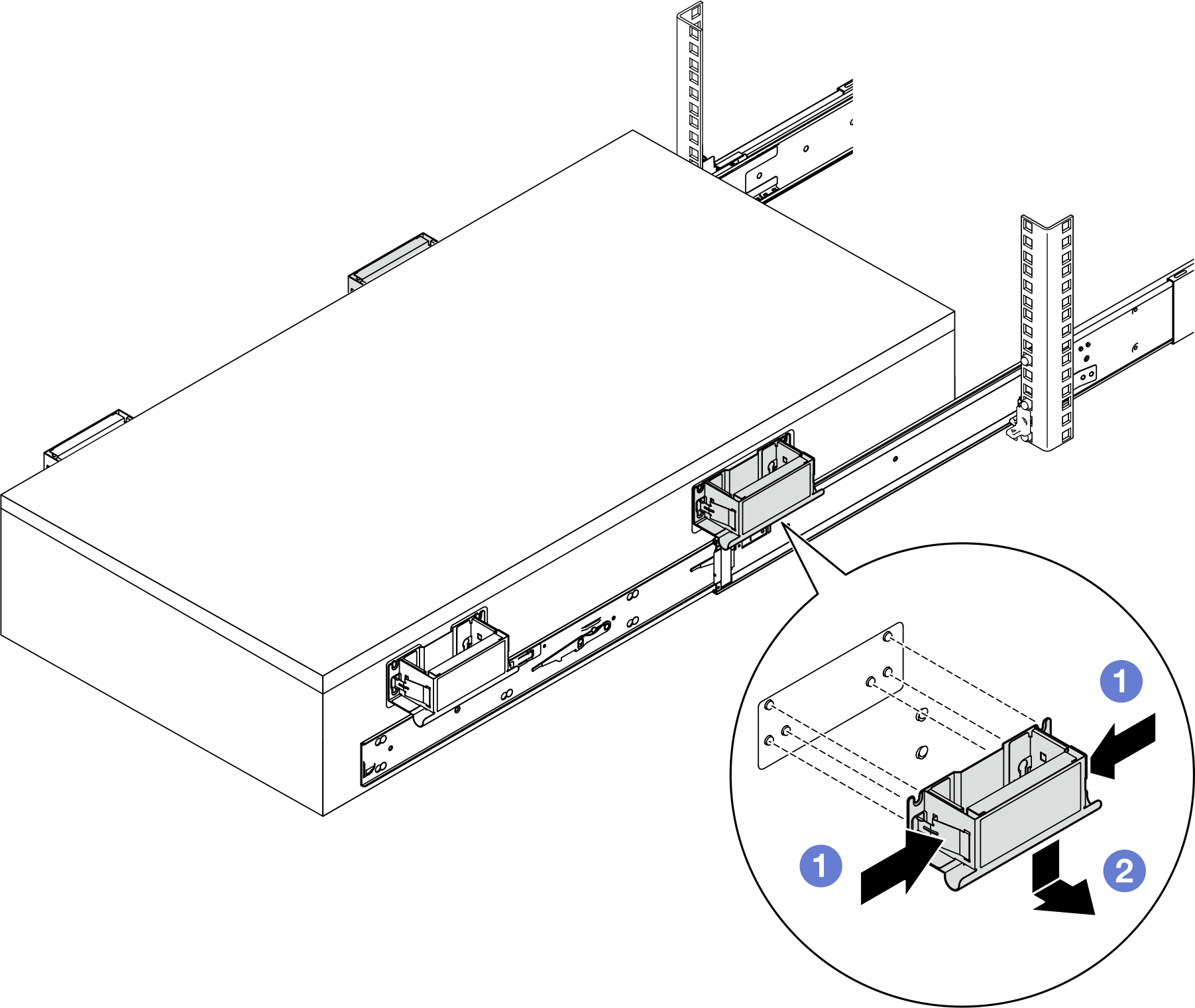
Remove the rear lift handle
| |
Note: Make sure to remove both rear lift handles before proceeding with the slide. |
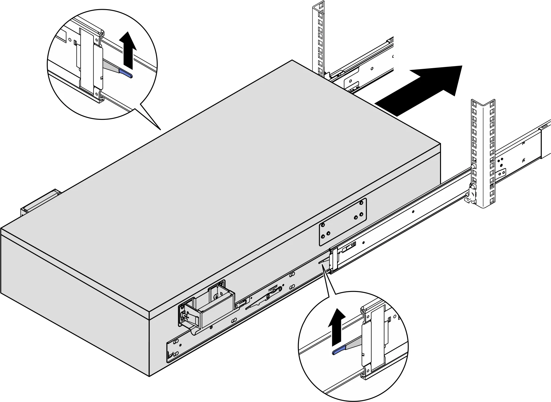
Lift the first pair of slide locks to continue sliding the server in until the rails click into place
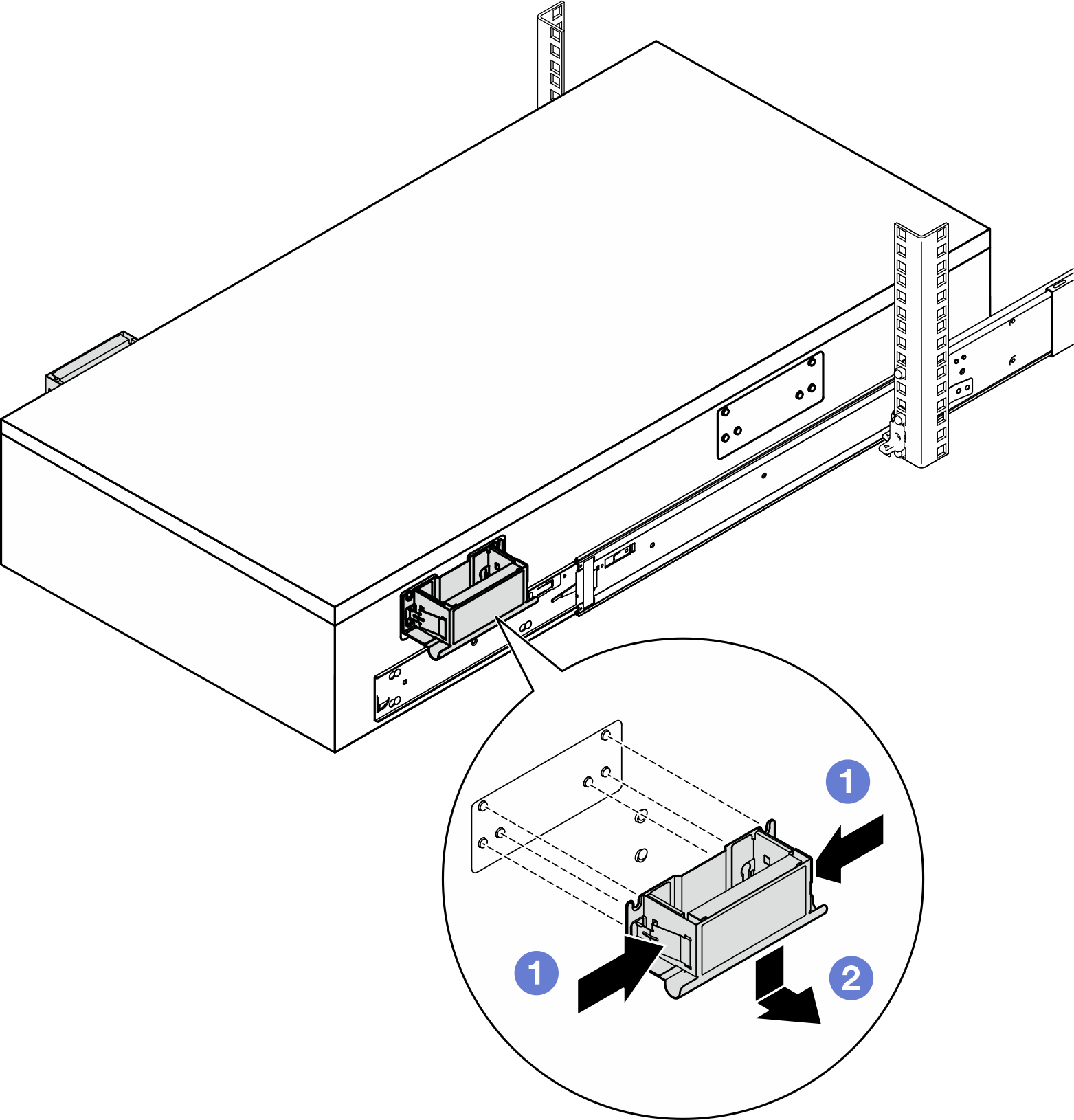
Remove the front lift handle
| |
Note: Make sure to remove the two front lift handles before proceeding to slide the server in. Warning: Do not lift the second pair of slide locks until all handles have been properly removed. |
Lift the second pair of slidelocks and continue to slide the server in
Repeat the above operation for the auxiliary chassis (upper chassis).
Once both chassis are in place, connect the front cables
Connect 8 external UPI cables to the main chassis. Please ensure that the cable matches the number and pattern shown on the UPI label
Close the UPI cover on the main and secondary chassis
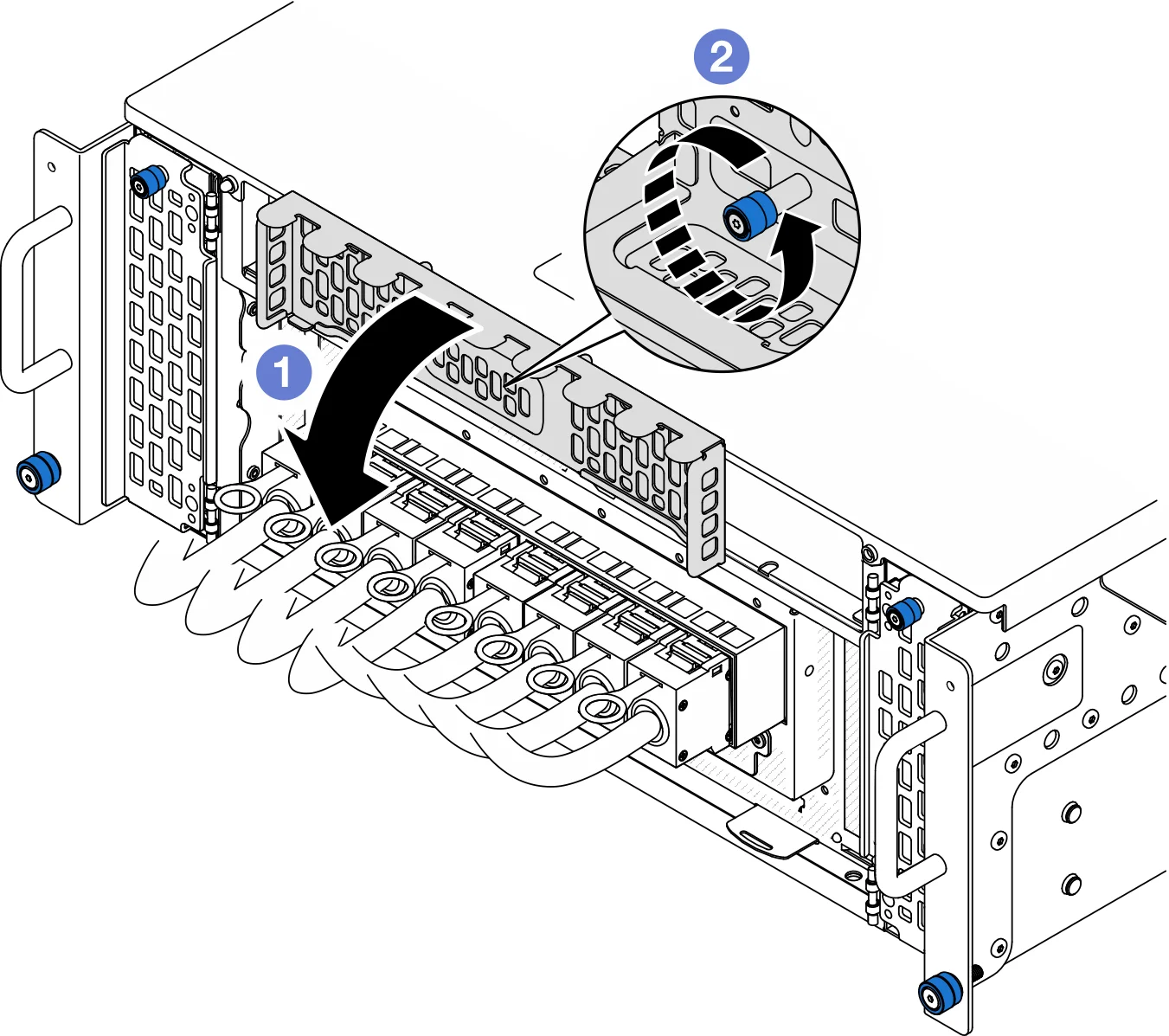
- Close the UPI cover.
- Tighten the thumbscrews to secure the UPI cover. Use a screwdriver if needed
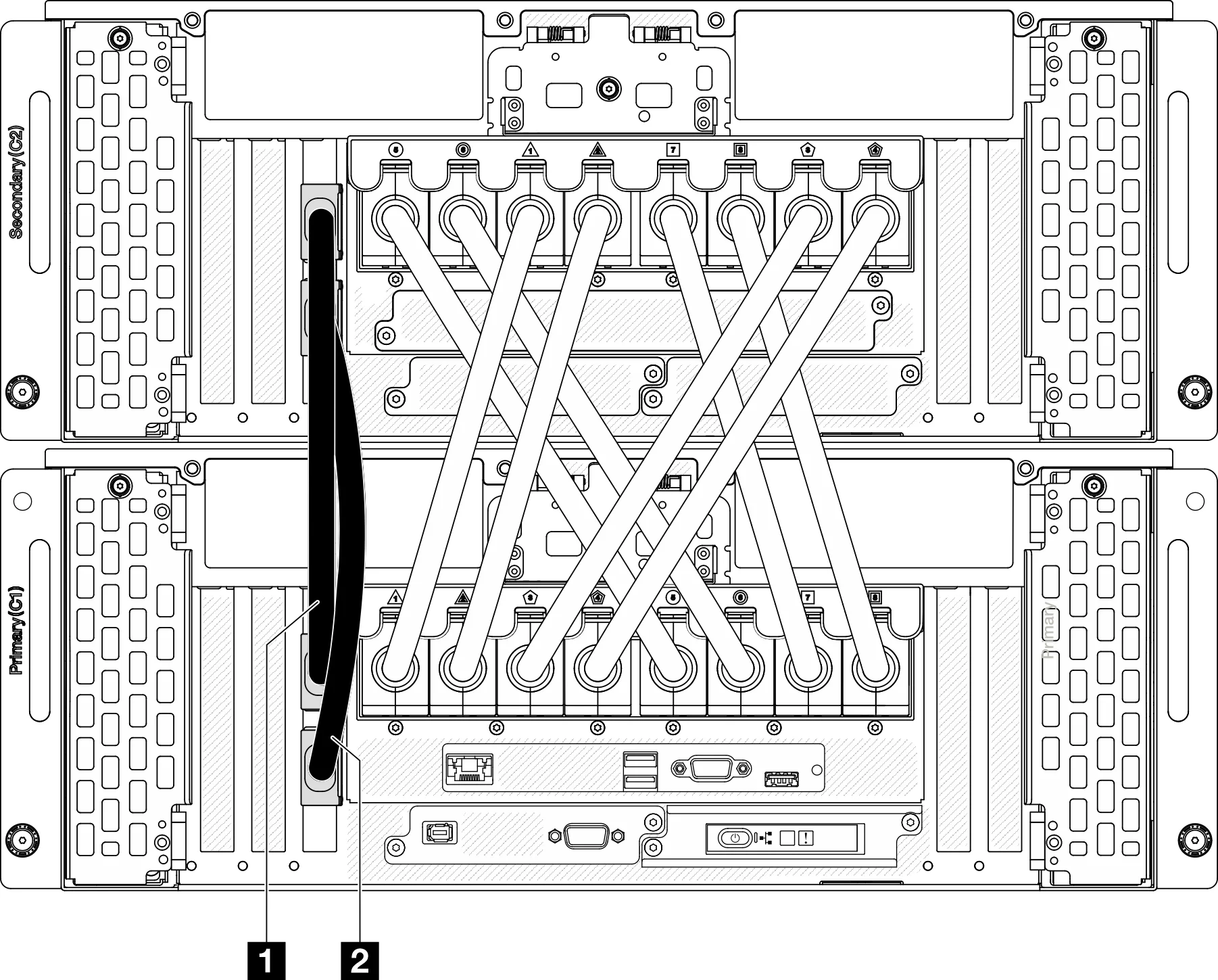
Connect the sideband cables to the main and secondary chassis
Connect all remaining external cables to the chassis, including rear data cables and power cables (first to the power cable of the auxiliary chassis (upper chassis) and then to the power cord of the main chassis (lower chassis))
Put back all previously removed components
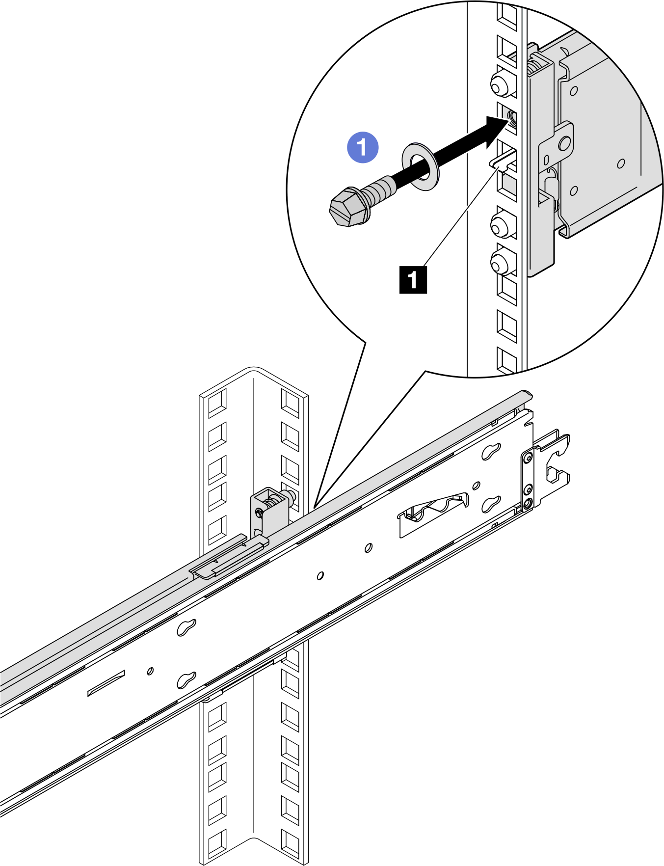
Secure the server to the rack
back
| front
|
1. Hook slide lock | |
Note: When operating as described below, use a flat head, allen socket, or Phillips screwdriver.
| |
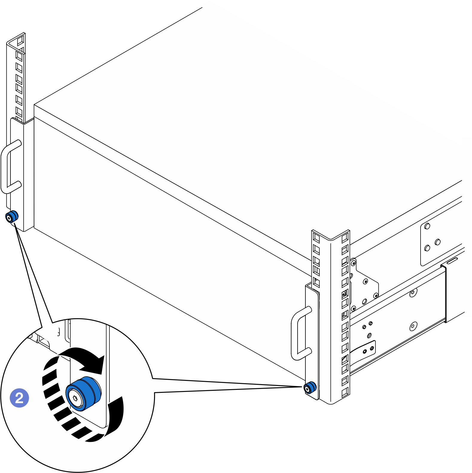
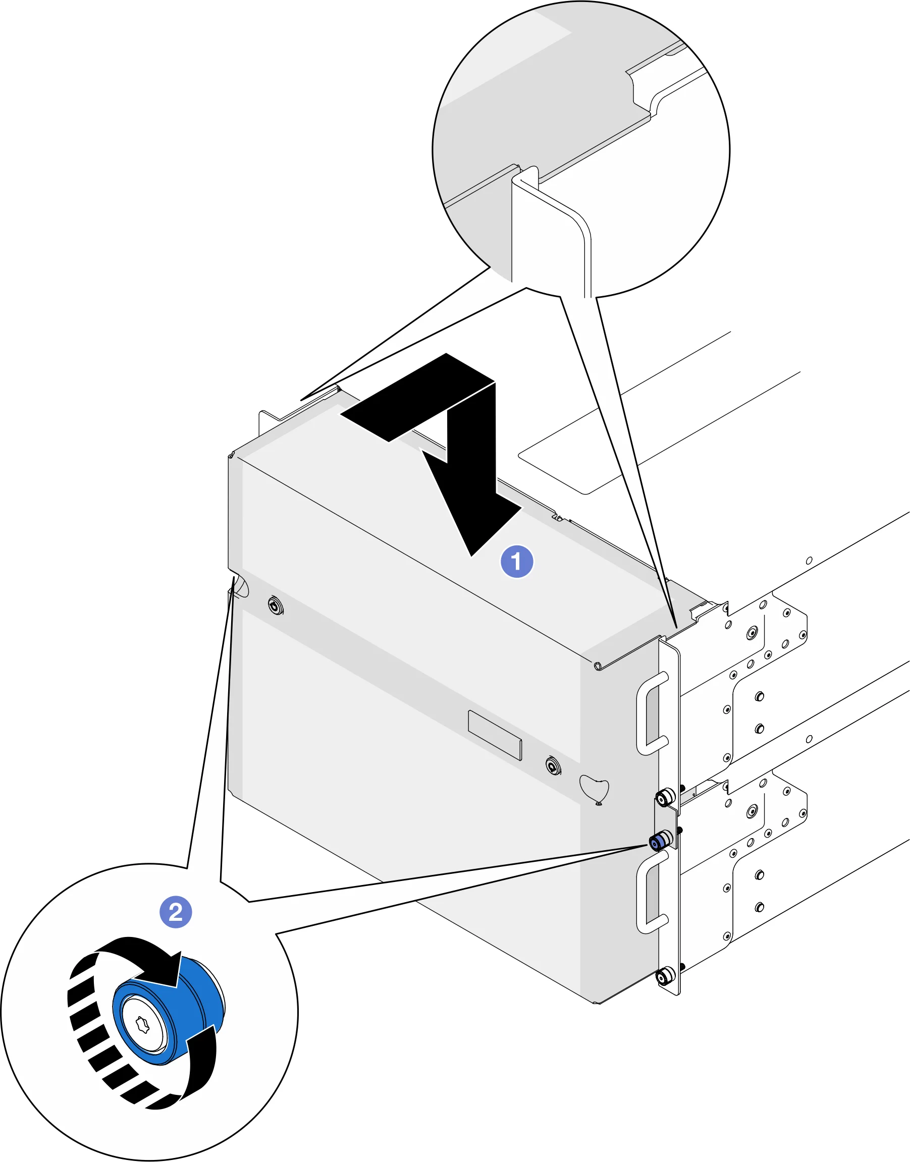
If the safety baffle has been removed, put it back on