DIMM Replacement - Action Plan - SA5212M5
1.Part Info
|
Catalog |
Details |
|
PN#/FRU# |
HMA84GR7CJR4N-WM |
|
DESC |
Memory_SK_32G_DDR4-2933ER_2R4_C36J |
|
QTY |
1 |
2.Basic Info
|
Item |
Details |
|
Downtime Required? |
Need Downtime |
|
Estimated Hours |
2H |
|
Tools Required-Hardware |
Screwdriver tool kit,pen, |
|
Tools Required-Software |
No |
|
Failed Part Catalog |
Memory |
|
Failed Part Location |
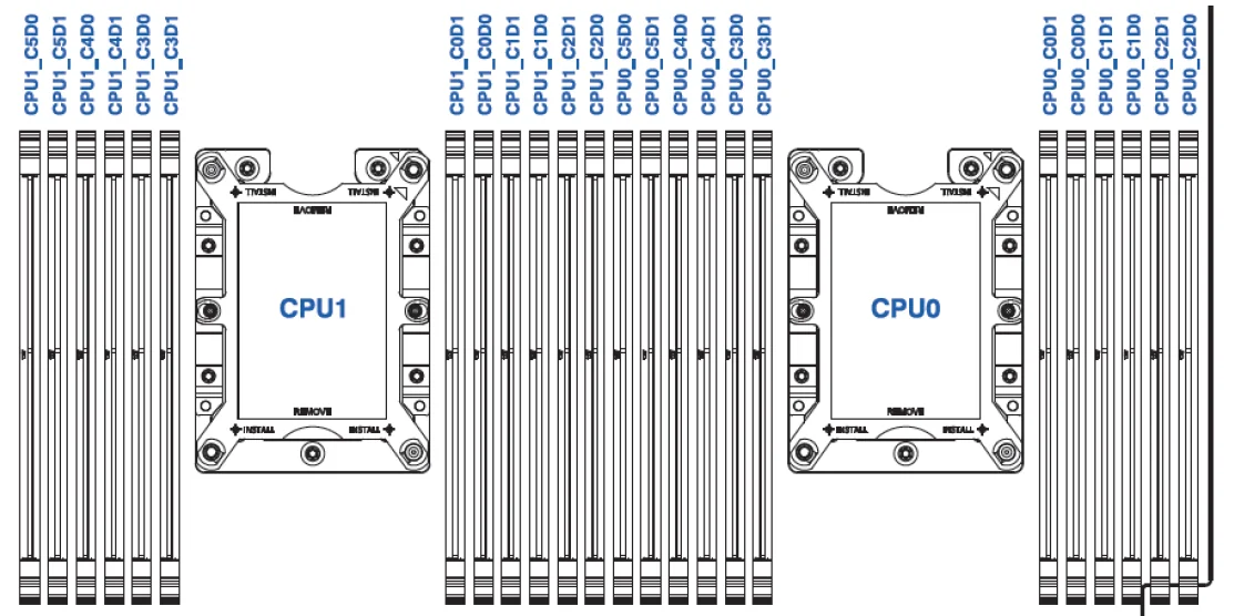
CPU0 C2 D0 |
3.Action Plan:
|
1. Confirm that the equipment serial number is for this maintenance equipment.
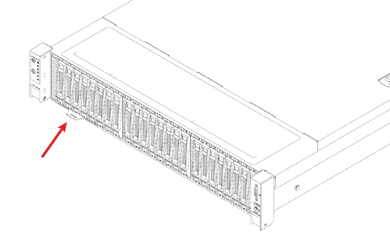
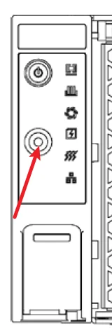
2.Mark the equipment to be maintained and press the positioning indicator button.
After pressing the button, the UID indicator lights in front and behind the device will light up
3.Use a marker pen or photography tool to record the connection status of the rear cable. In the following steps, it is necessary to restore the cable connection to the customer's settings.
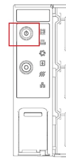
4.Observe the status of the power on indicator light. If it is constantly green, please remind the customer to turn off the device.
If it is constantly orange, continue to the next step
5.Record and remove all rear data cables and power cables, Confirm that there are no cables connected to the device
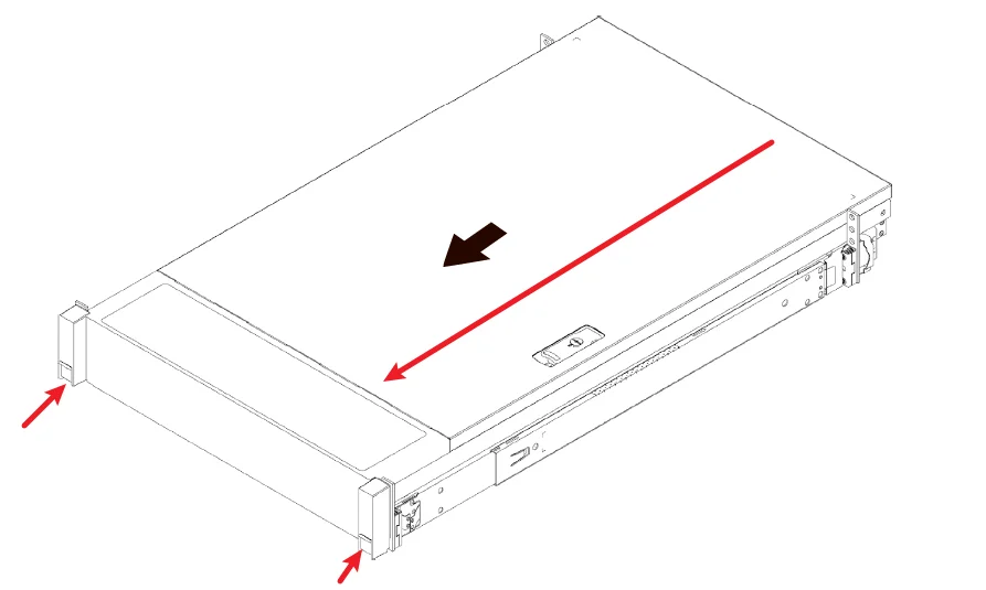
6.Press the unlock spring on both sides of the server and carefully pull the server out of the chassis.
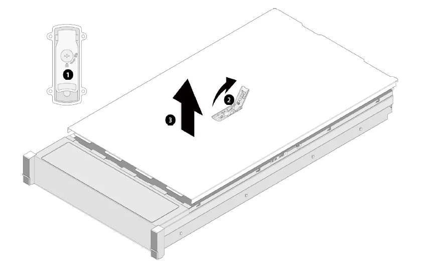
7.a. Use a Phillips screwdriver to unlock the top cover of the computer case.
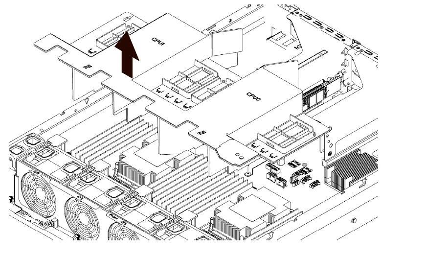
8.a. Lift the radiator air guide cover
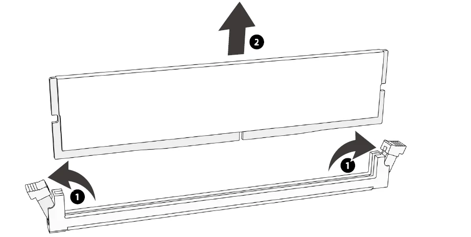
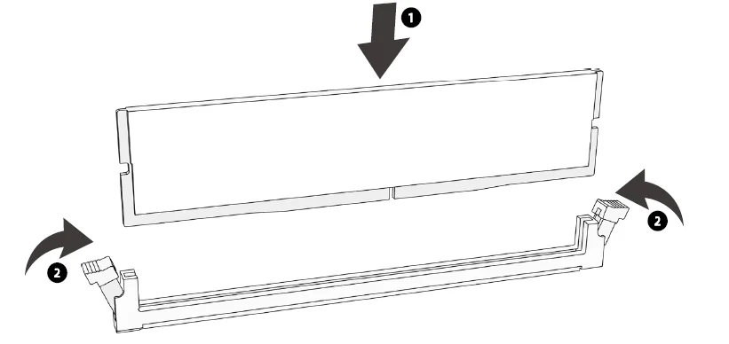
9.Remove the faulty memory at the specified location according to previous instructions Install the spare memory to the disassembly position
10.Install the radiator grille and chassis cover onto the chassis
11. Push the chassis into the cabinet 12. Restore the cable to customer settings 13.Notify the customer to initiate device inspection
|

4. Verification :
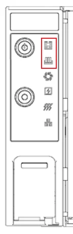
| Observe whether there are any abnormal indicator lights on after the device is turned on
|
5. Reference Link/Doc:
| N/A |
6. Failure Part Location:
|
|